GE HEALTHCARE
DIRECTION 2307224-100, REVISION 6DISCOVERY LS SYSTEM SERVICE MANUAL
Chapter 7 - Gantry Page 239
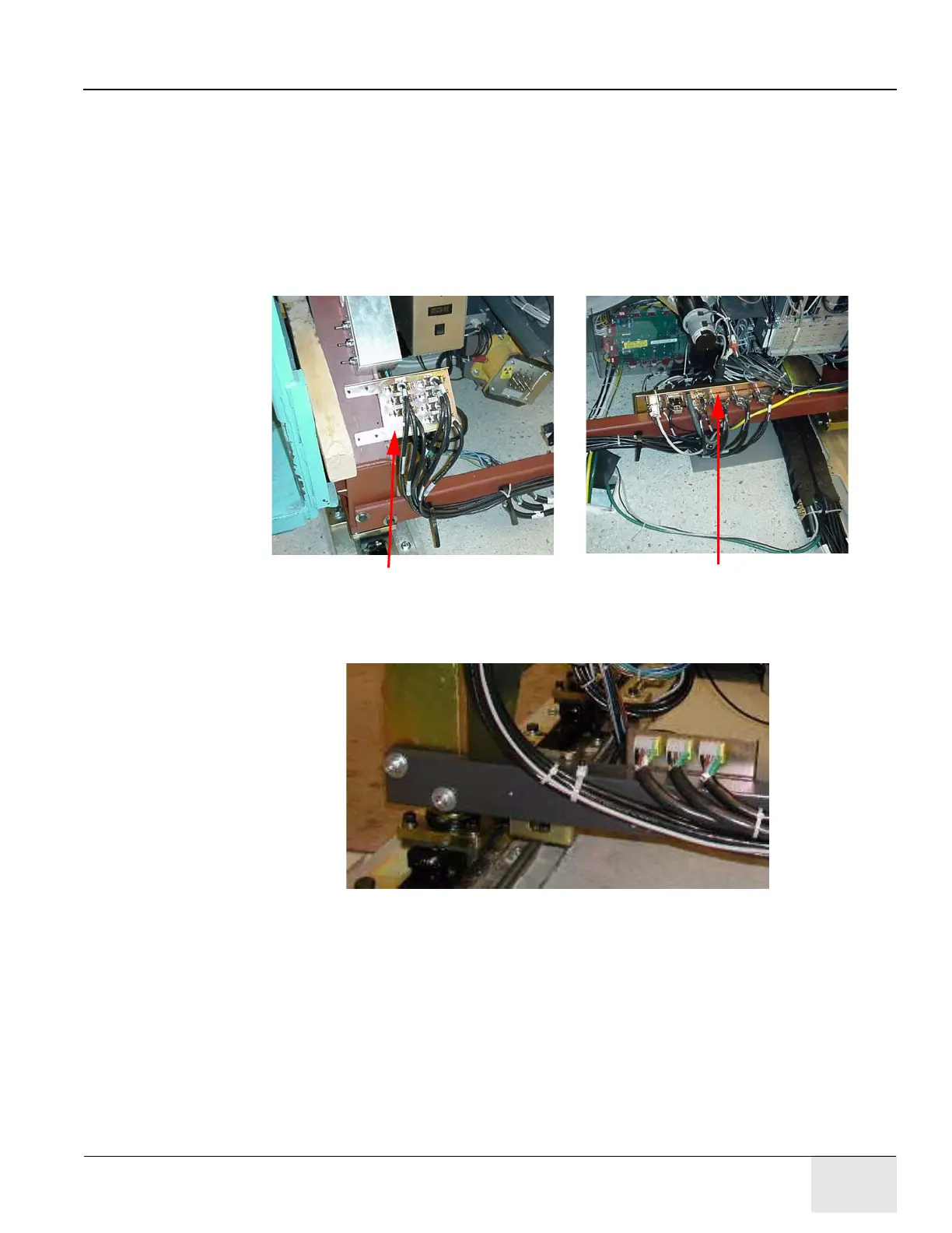
7.5.3 Connecting External PET Cables & New CT-PET Cables to New A36-1,
A36-2, A37-1 Panels
• The external PET cables and the new CT-PET cables are connected to the new A36-1, A36-
2, and A37-1 brackets as shown in Figure 7-19.
• Power cables, connected to the A36-2 bracket, should be routed under the legs crossbeam.
• Other cables should be routed on the external side of the legs crossbeam.
Note: Do not route any cables on the internal or upper side of the legs crossbeam. Connect the cables so
that their minimum bending radius is 12.5 mm.
Figure 7-19: External Cables Connections to A36-1 and A37-1 Brackets
Figure 7-20: Power Cable Connections to A36-2 Bracket
• The grounding cable is connected to the new PET left leg.
• Connect "Terminator RHK", P/N 2295966, to GAN1 A37 J12.
A36-1 Bracket
A37-1 Bracket