Intel® Server D50DNP Family Integration and Service Guide
120
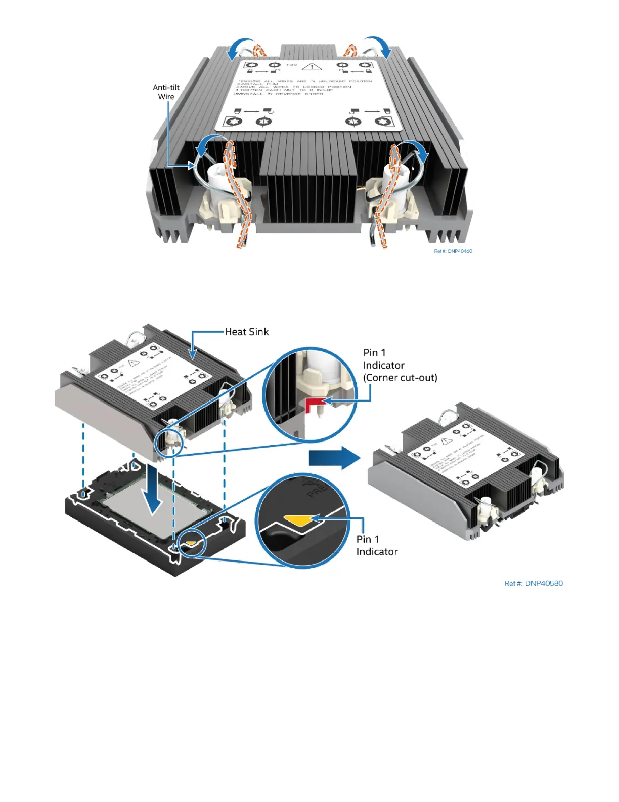
Figure 139. Processor Heat Sink Anti-tilt Wires in the Outward Position
7. Set the anti-tilt wire over each of the four heat sink fasteners to their outward position.
Figure 140. Pin 1 Indicator of Processor Carrier Clip
8. Align the Pin 1 indicator of processor carrier clip with one of the diagonally cut corners on the base of
the heat sink. Or (if present) look for the Pin 1 indicator on the corner of the heat sink label.
9. Gently press down the heat sink onto the processor carrier clip until it clicks into place.
10. Ensure that all four heat sink corners are securely latched to the processor carrier clip tabs.