Intel® Server D50DNP Family Integration and Service Guide
44
Caution: Do not touch the socket pins. The pins inside the processor socket are extremely sensitive.
A damaged processor socket may produce unpredictable system errors.
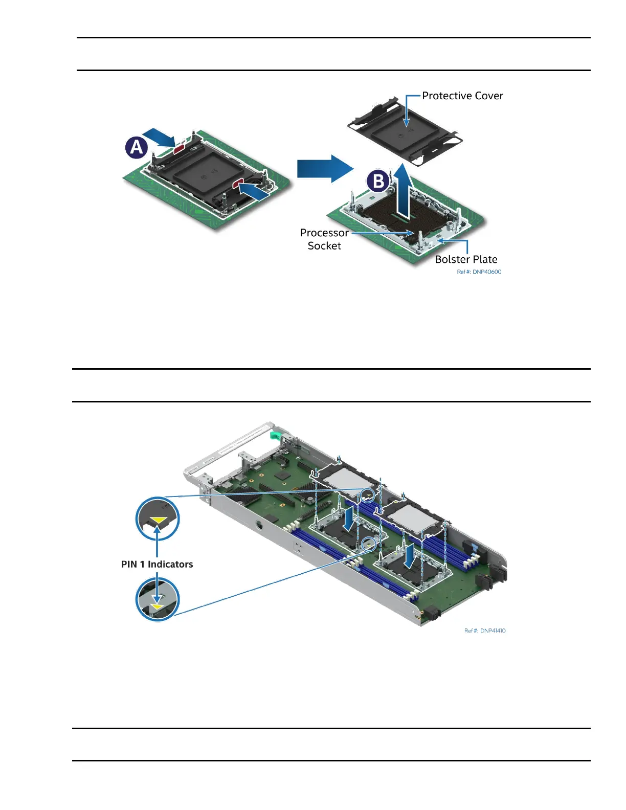
Figure 35. Socket Protective Cover Removal
5. Remove the socket protective cover by squeezing the finger grips (see Letter A) and pulling the cover
up (see Letter B).
6. Ensure that the socket is free of damage or contamination before installing the PHM.
Caution: If debris is observed, blow it away gently with an air blower. Do not use tweezers or any
other hard tools to remove the debris.
Figure 36. Align Processors and Processor Carrier Clips with Sockets
7. Align the Pin 1 indicators of the processor carrier clip and processor with the Pin 1 indicator on the
bolster plate.
8. Lower the processors onto the socket assembly.
Caution: Processor socket pins are delicate and bend easily. Use extreme care when placing the
processor and carrier clip onto the processor socket. Do not drop it.