Intel® Server D50DNP Family Integration and Service Guide
42
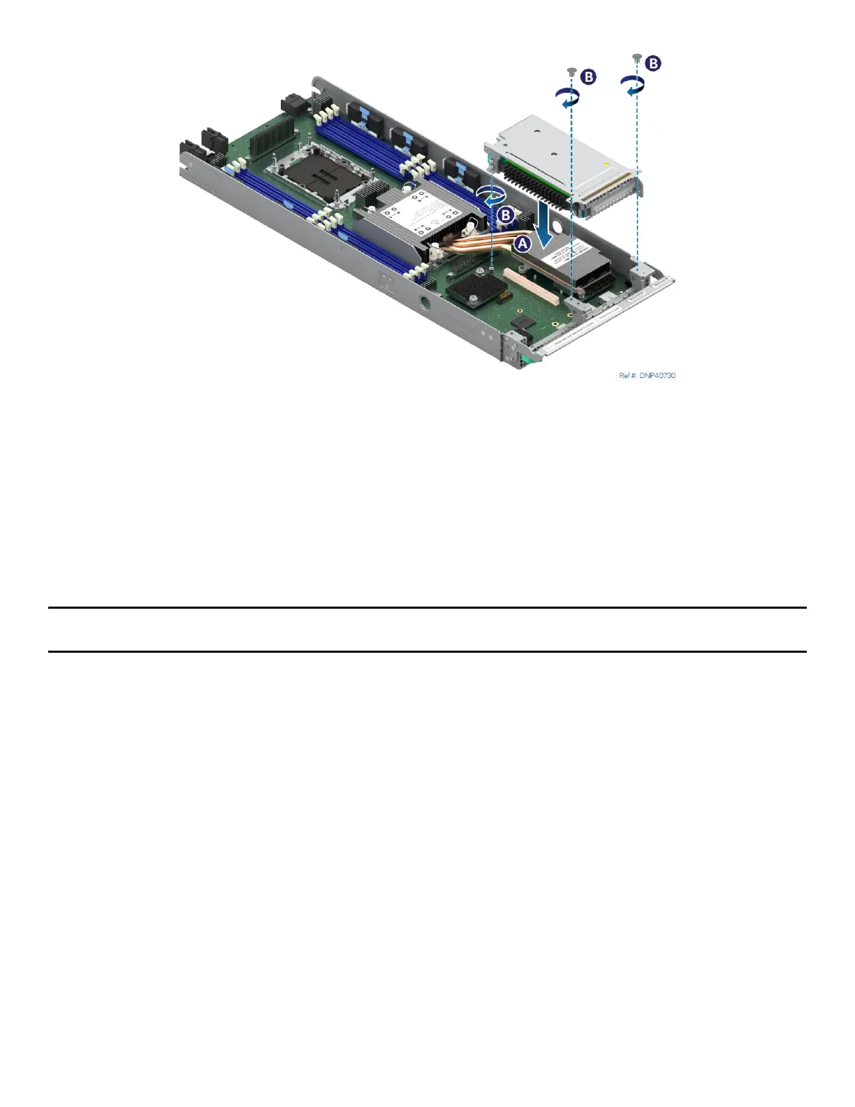
Figure 32.Installing a Riser Assembly
13. Align the riser card to the riser slot on the server board (see Letter A).
14. Carefully push down on the riser assembly until the riser card is securely seated into the riser slot.
15. Ensure that screw holes of the riser assembly are aligned with the mounting holes of the module.
16. Using Phillips screwdriver #2 tighten the captive screw at the back of the riser assembly to 5 in-lb.
(see Letter B)
17. Using Phillips screwdriver #1 install two screws to secure the riser assembly to the front of the
module. Tighten to 5 in-lb. (see Letter C).
18. Reinstall the air duct (see Section 2.1.2).
Note: Intel strongly recommends installing both processors. If only one processor is installed, do not install a
processor heat sink on an empty socket.
2.2.5 Assembly and Installation for Liquid-Cooled Configurations
Components Required
• 4
th
Gen Intel® Xeon® Scalable processors or Intel® Xeon® CPU Max Series processors in shipping tray
• Processor carrier clips matching processor type
Required Tools and Supplies
• Anti-static wrist strap and conductive workbench pad (recommended)
• ESD gloves
For liquid-cooled system configurations, the processor is cooled through cold plates that are part of a
liquid-cooling loop. The following steps only cover the processor and processor carrier clip installation to
the socket assembly. The installation of the processor cold plates is explained in Section 2.3.