Intel® Server D50DNP Family Integration and Service Guide
129
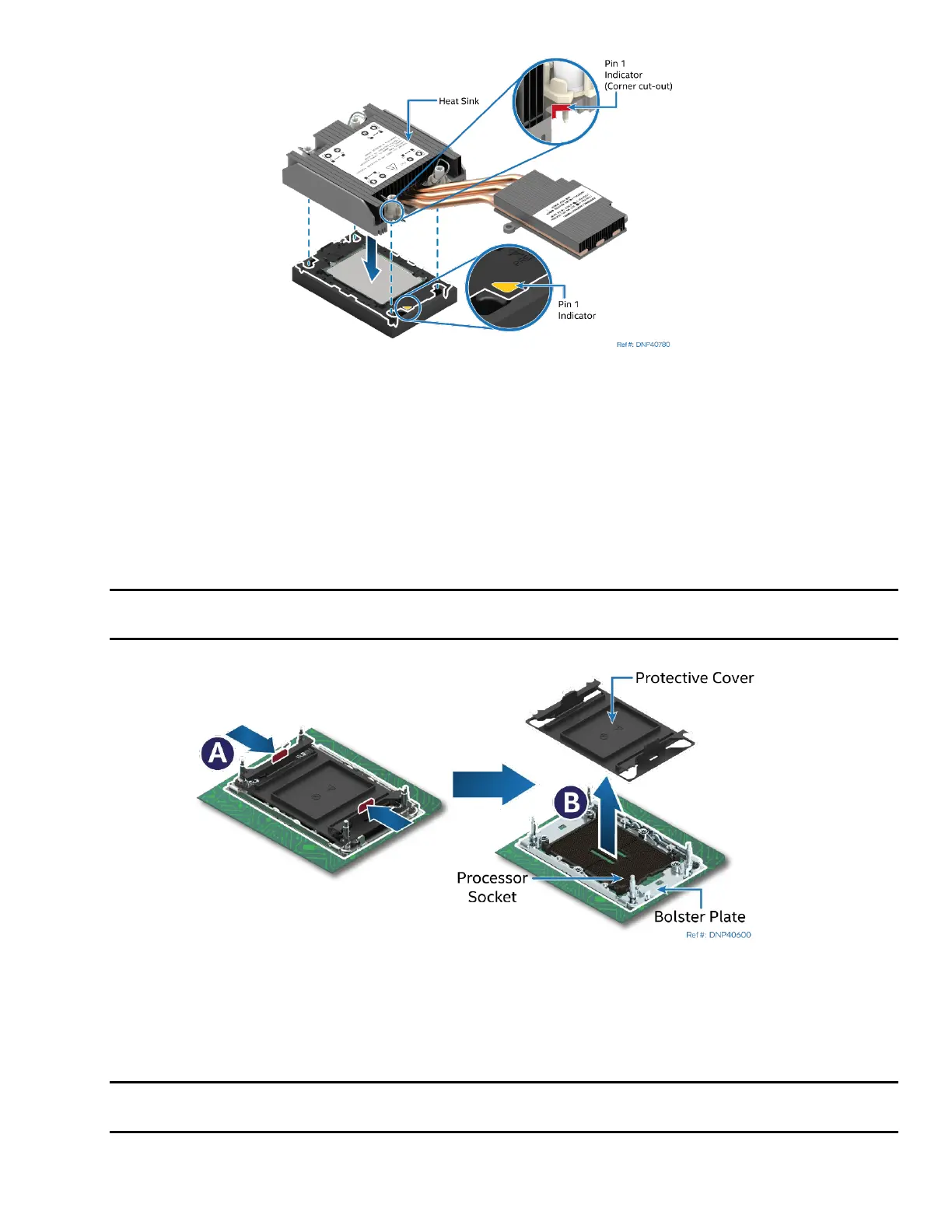
Figure 156. Pin 1 Indicator of Processor Carrier Clip
8. Align the Pin 1 indicator of the processor carrier clip with one of the diagonally cut corners on the
base of the heat sink. Or (if present) look for the Pin 1 indicator on the corner of the heat sink label.
9. Gently press down the heat sink onto the processor carrier clip until it clicks into place.
10. Ensure that all four heat sink corners are securely latched to the processor carrier clip tabs.
7.3.2.4 PHM Installation
1. If installed, remove the plastic cover from the processor socket.
Caution: Do not touch the socket pins. The pins inside the processor socket are extremely sensitive. A
damaged processor socket may produce unpredictable system errors.
Figure 157. Socket Protective Cover Removal
2. Remove the protective cover by squeezing the finger grips (see Letter A) and pulling the cover up
(see Letter B).
3. Ensure that the socket is free of damage or contamination before installing the PHM.
Caution: If debris is observed, blow it away gently with an air blower. Do not use tweezers or any
other hard tools to remove the debris.