Intel® Server D50DNP Family Integration and Service Guide
128
1. Align the Pin 1 indicator on the processor carrier clip with the Pin 1 indicator of the processor.
2. With the processor still in its tray, place the processor carrier clip over the processor.
3. Gently press down simultaneously on two opposite sides of the processor carrier clip until it clicks in
place.
4. Repeat step 3 for the other two sides.
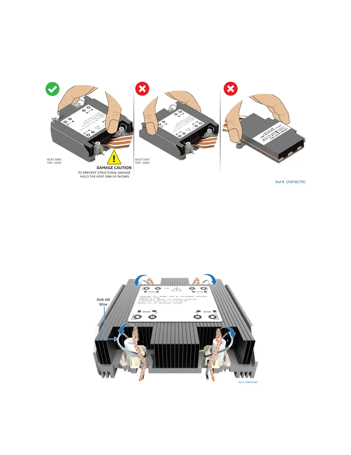
5. Locate the processor heat sink. To avoid damage, grasp it by its narrower sides as shown.
Figure 154. Processor Heat Sink Handling
6. Place the heat sink bottom side up onto a flat surface.
If reusing an existing heat sink:
• Properly clean off existing thermal interface material (TIM) from the bottom of the heat sink
• Apply new TIM (Honeywell PTM7000*)
If using a new heat sink, remove the plastic protective film from the Thermal Interface Material (TIM).
Figure 155. Processor Heat Sink Anti-tilt Wires in the Outward Position
7. Set the anti-tilt wires to their outward position.