Intel® Server D50DNP Family Integration and Service Guide
83
3.8.3 M.2 SSD Heat Sink Installation for Air-Cooled Configurations
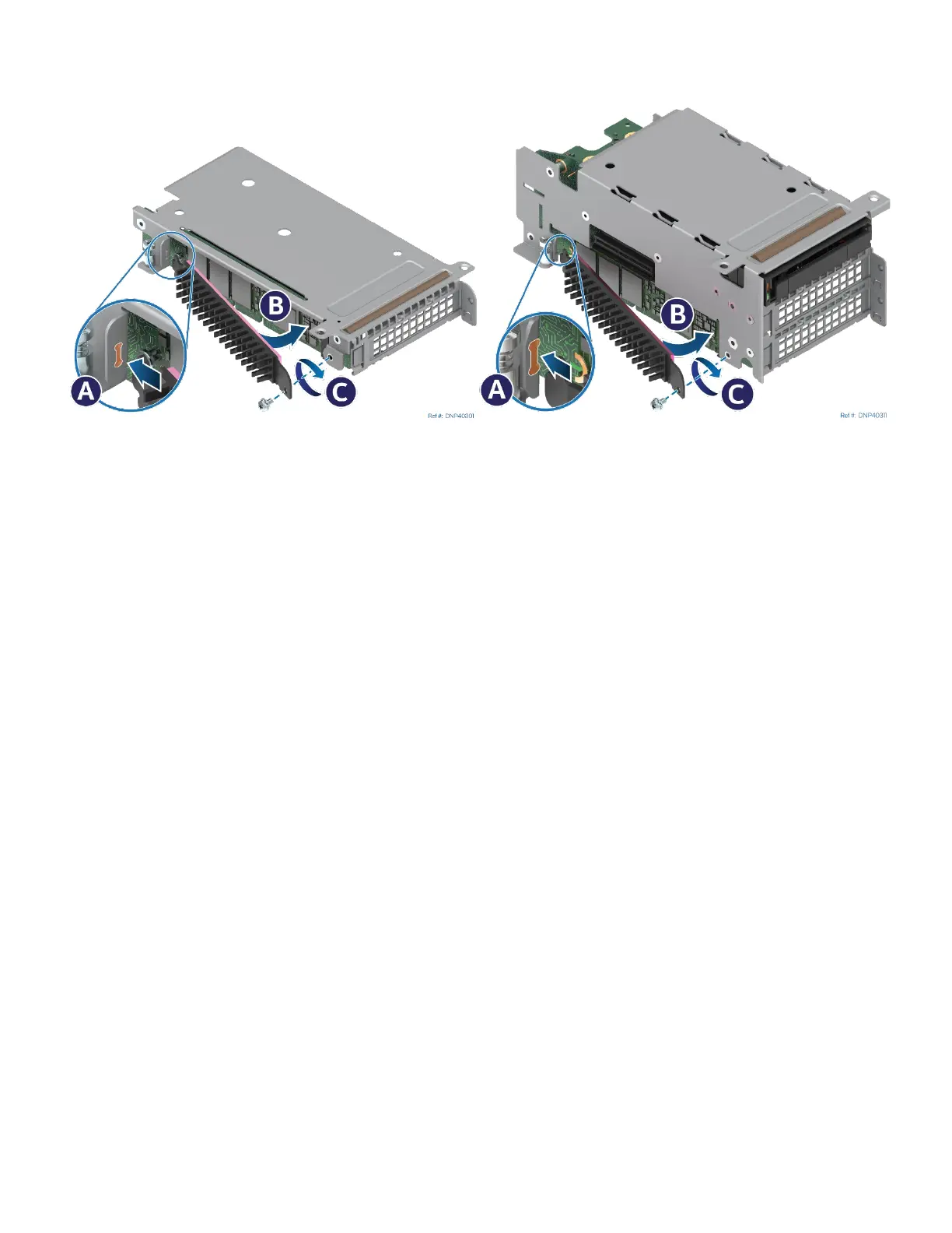
Figure 95. Installing M.2 Heat Sink
1. Peel off the protective film from the long thermal pad attached to the heat sink.
2. Insert the tab at the edge of the heat sink into the slot on the riser assembly (see Letter A) making sure
the heat sink side covered with the thermal pad is facing the M.2 SSD.
3. Push the loose end of the heat sink towards the SSD (see Letter B).
4. Secure the heat sink to the riser assembly with the previously removed screw (see Letter C).
3.8.4 Riser Bracket Installation for Liquid-Cooled Configurations
Required Tools and Supplies
• PCIe* / SATA M.2 SSD
• M.2 cold plate kit for each M.2 SSD (iPC DNPM2LCHS)
• Anti-static wrist strap and conductive workbench pad (recommended)
• Phillips* head screwdriver #1
• 3/16” hex nut driver
The M.2 SSD cold plate kit DNPM2LCHS includes:
• M.2 SSD cold plate
• Two thermal interface material pads (Laird Tflex HD7100*)
• Two M3 pan-head screws (black)
• Riser bracket
• Three spare thermal strips