Intel® Server D50DNP Family Integration and Service Guide
39
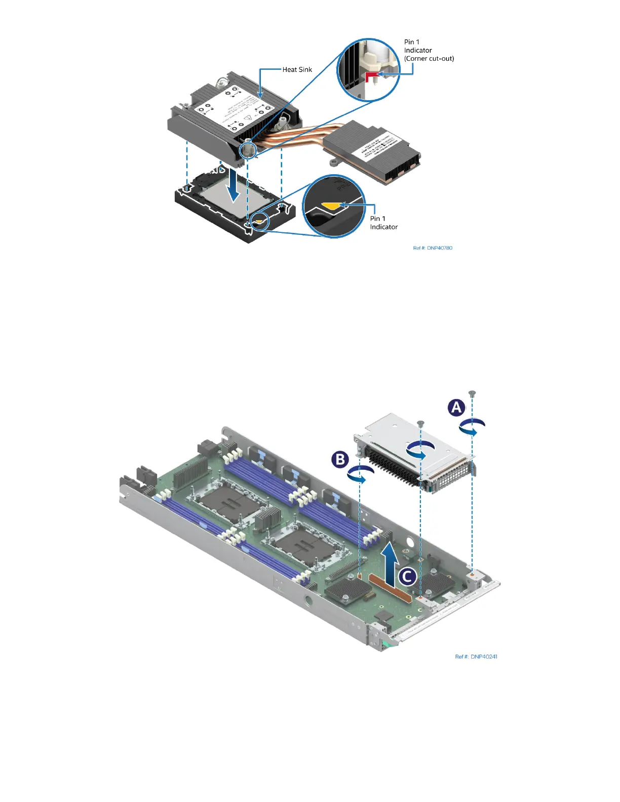
Figure 26. Pin 1 Indicator Alignment
9. Align the Pin 1 indicator of processor carrier clip with one of the diagonally cut corners on the base of
the heat sink. Or (if present) look for the Pin #1 indicator on the corner of the heat sink label.
10. Gently press down the heat sink onto the processor carrier clip until it clicks into place.
11. Ensure that all four heat sink corners are securely latched to the processor carrier clip tabs.
2.2.4.2 EVAC PHM Installation
Figure 27. Removing a Riser Assembly
1. Using Phillips #1 screwdriver remove two screws that secure the right riser assembly to the front of
the module (see Letter A).
2. Using Phillips screwdriver #2 loosen the captive screw at the back of the riser assembly. (see Letter B)
3. Carefully remove the riser assembly by lifting it up and away from the module (see Letter C).