Intel® Server D50DNP Family Integration and Service Guide
30
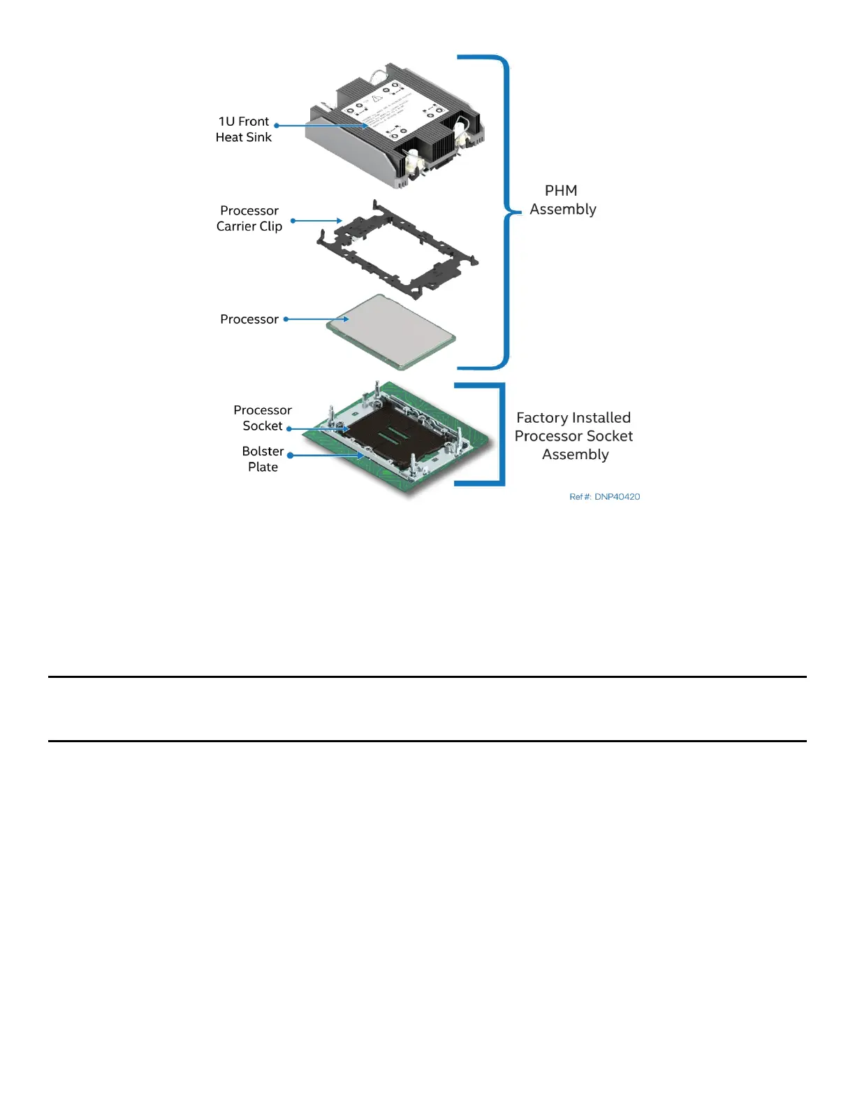
Figure 11. Processor Components and Processor Socket Reference Diagram with Standard Heat Sink
To properly assemble the PHM and to install it onto the server board, the procedures described in the
following sections must be followed in the order specified. These instructions assume that all PHM
components are new, and the Thermal Interface Material (TIM) is already applied to the bottom of the heat
sink.
2.2.3.1 Processor Heat Sink Module (PHM) Assembly
Caution: Full ESD precautions should be followed to perform assembly of the PHM and installation of the
PHM to the server board. Wear ESD gloves to prevent electrostatic damage and oxidation or foreign
materials on processor package and land pads.
Each component within the PHM assembly includes a Pin 1 indicator. Pin 1 indicator alignment between all
components is required throughout the assembly process.