Intel® Server D50DNP Family Integration and Service Guide
35
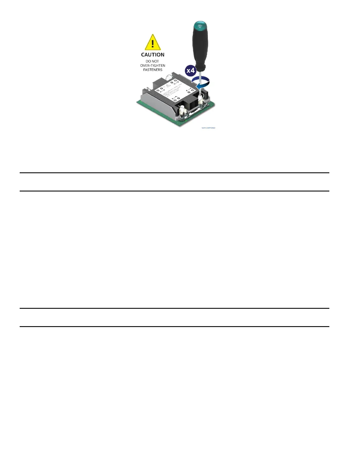
Figure 20. Tighten Heat Sink Fasteners
8. Using a T30 Torx* screwdriver, tighten the heat sink fasteners to 8 in-lb. No specific sequence is
needed for tightening. General diagonal bolt tightening order can be used.
Note: Intel strongly recommends installing both processors. If only one processor is installed, do not install a
processor heat sink on an empty socket.
2.2.4 Assembly and Installation for EVAC Heat Sinks
Components Required
• 4
th
Gen Intel® Xeon® Scalable processors or Intel® Xeon® CPU Max Series processors in shipping tray
• Processor carrier clips matching processor type
• 1U EVAC processor heat sink (front) and 1U standard processor heat sink (back)
Required Tools and Supplies
• Anti-static wrist strap and conductive workbench pad (recommended)
• Adjustable torque T30 Torx* screwdriver
• ESD Gloves
• Phillips* head screwdriver #1 and #2
Note: The following procedures show the installation for the 1U EVAC processor heat sink (front). To install
the 1U standard processor heat sink (back), follow the procedures in Section 2.2.3.
A processor heat sink module (PHM) assembly and processor socket assembly (or “loading mechanism”) are
necessary to install a processor onto the server board. Figure 21 identifies each component associated with
the PHM and processor socket assemblies.