Intel® Server D50DNP Family Integration and Service Guide
164
22. Carefully unpack a new liquid-cooling loop.
23. Remove the protective covers from the PCIe* add-in card cold plate and from the CPU cold plates.
24. Ensure that the thermal interface material (TIM) for each cold plate is in place and the plastic protective
film is removed.
Important Note: The liquid-cooling loop comes from the factory with a plastic carrier attached. The
carrier is designed to be used during the installation and removal of the liquid-cooling loop in the
module. After the liquid-cooling loop is installed in the module, the plastic carrier needs to be removed
from it. Keep the plastic carrier for the liquid-cooling loop removal, if needed in the future.
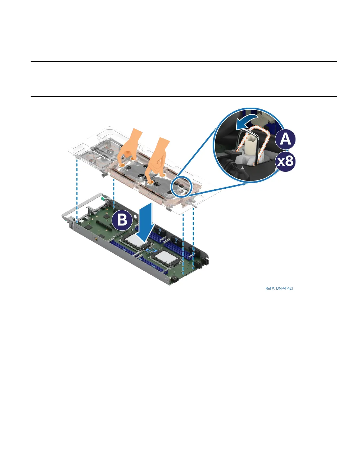
Figure 219. Installing Liquid-Cooling Loop
25. Set all eight anti-tilt wires on the cold plates to the inward position (see Letter A).
26. With your fingers, hold the liquid-cooling loop carrier and carefully place it into the module (see Letter B).
Ensure that the processor cold plates are properly aligned with the bolster plate’s alignment pins.