Intel® Server D50DNP Family Integration and Service Guide
45
2.3 Liquid-Cooling Loop Installation (D50DNP1MHCPLC Module)
The liquid-cooled systems are designed to connect to a non-Intel coolant distribution unit using Staubli*
SCG 09 quick disconnect couplings. The internal cooling for this configuration is done using a liquid-cooling
loop. To maintain system thermals for liquid-cooled modules, the liquid-cooling loop must always be in
place when the system is operational.
The liquid-cooling loop kit for compute module (DNPLCLPCM) includes:
• Passive cold plate loop assembly
• Plastic carrying case
• Memory cooling kit
The installation of the liquid-cooling loop assumes that the processors and the processor clips are already
installed in the sockets as explained in Section 2.2.5.
Note: Liquid-cooling loop installation requires that no DIMMs are installed in the memory slots.
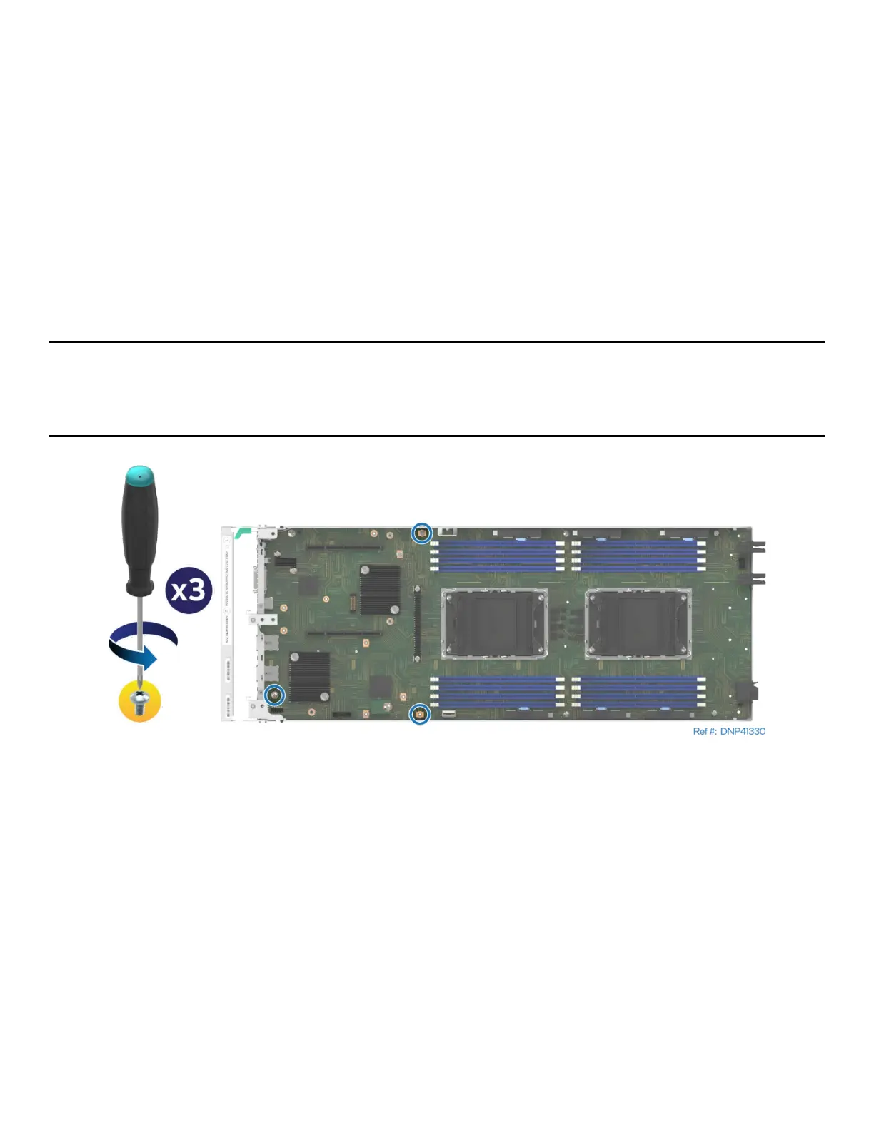
Important Note: As part of the shipping process, there are screws occupying the screw holes on the server
board as shown on the following figure. Remove those screws before starting the liquid-cooling loop
installation procedures described in this section.
Figure 37. Screws to be removed before the installation
The cooling components for liquid-cooled systems are shown in the following figure.