Intel® Server D50DNP Family Integration and Service Guide
135
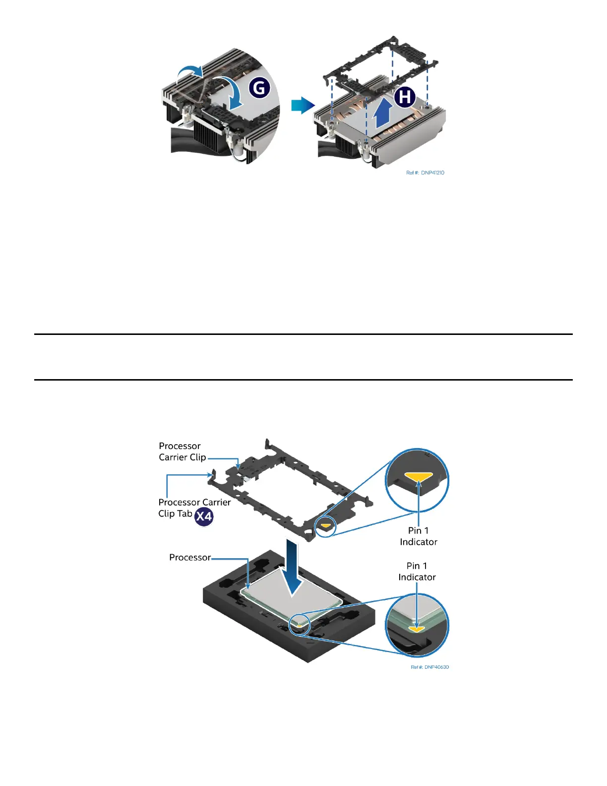
Figure 168. Processor Carrier Clip Removal from Processor Cold Plate
10. Return the lever to the original position (see Letter G).
11. Unlatch the hook on each corner of the processor carrier clip and lift it from the processor cold plate (see
Letter H).
To properly reassemble the new processor and processor carrier clip and install them onto the server board,
the following procedures must be followed in the order specified. These instructions assume that the
processor cold plate has the necessary thermal interface material (TIM) Dow Corning TC-5622* already
applied to the clean bottom of the cold plate.
Caution: Full ESD precautions should be followed to perform assembly and installation of the PHM to the
server board. Wear ESD gloves to prevent electrostatic damage and oxidation or foreign materials on
processor package and land pads.
The new processor, processor carrier clip, and processor socket all have a Pin 1 indicator. Pin 1 indicator
alignment between all these components is required throughout the assembly process.
Figure 169. Installing Processor Carrier clip onto Processor – Part 1
12. Align the Pin 1 indicator on the processor carrier clip with the Pin 1 indicator of the processor.
13. With the processor still in its tray, place the processor carrier clip over the processor.