Intel® Server D50DNP Family Integration and Service Guide
52
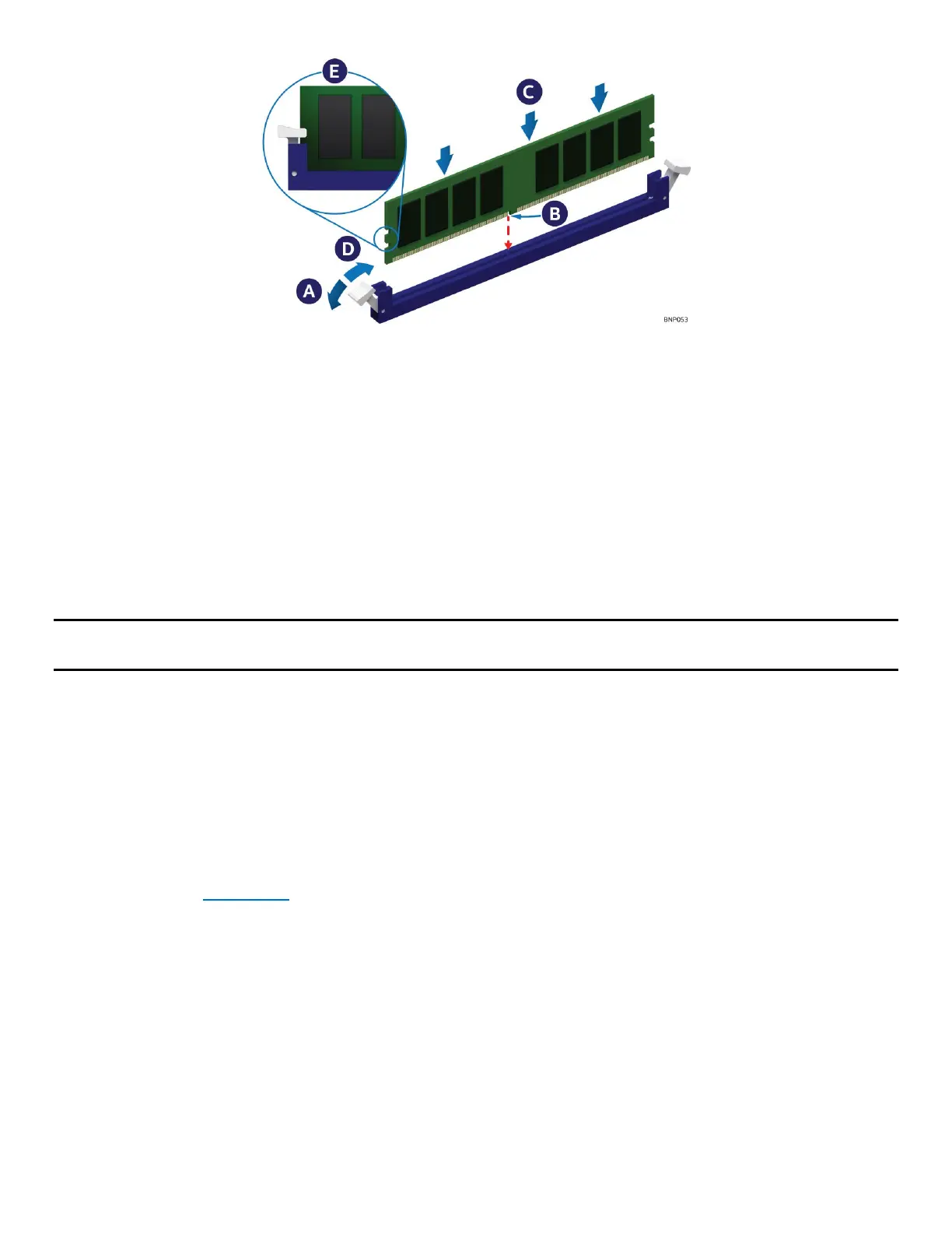
Figure 47. Memory Module Installation
2. Ensure that the ejection tabs at both ends of the memory slot are pushed outward to the open
position (see Letter A).
3. Carefully remove the memory module from its packaging, taking care to handle it only by its outer
edges.
4. Align the notch at the bottom edge of the memory module with the key in the memory slot
(see Letter B).
5. Insert the memory module into the memory slot. Using even pressure along the top edge, push down
on the memory module (see Letter C) until the ejection tabs of the memory slot snap into place (see
Letter D).
6. Ensure that the ejection tabs are firmly in place (see Letter E).
Note: Intel® Optane™ PMem devices require additional steps to enable and configure them. Refer to the
appropriate Intel® Optane™ PMem documentation to complete the installation process.
2.4.2 Memory Installation for Liquid-Cooled Modules
Required Tools and Supplies:
• Anti-static wrist strap and conductive workbench pad (recommended)
• DIMM latch tool (attached to the cooling loop)
• Memory cooling kit (included in the liquid-cooling loop box)
The liquid-cooled modules only support DDR5 SDRAM DIMMs. Intel® Optane™ PMem modules are not
supported. Before installing the DDR5 SDRAM DIMMs, ensure that the liquid-cooling loop is already installed
in the module (see Section 2.3
).
The memory cooling kit is included in the box with the liquid-cooling loop box. It includes sixteen DIMM
PMIC thermal pads, eight DIMM clips, and eight Mylar pads.