Intel® Server D50DNP Family Integration and Service Guide
64
3.4 Low-Profile Add-In Card Installation
The Intel® Server D50DNP Family supports either up to two (in 1U modules) or up to four (in 2U modules)
low-profile PCIe* add-in cards.
This section provides assembly and installation procedures for modules that require low-profile add-in card
installation. The following procedures apply to both 1U and 2U modules in both air-cooled and liquid-
cooled configurations.
Note: The PCIe* accelerator module D50DNP2MFALAC has additional support for up to four full-height, full-
length, double-width PCIe* accelerator cards. Follow the installation procedures in Section 3.6 for these
cards.
Available Riser Card Options
• 1U MCIO* (mini cool edge I/O) riser card (installed in 1U riser assembly) for 1U module
• 1U Standard riser card (installed in 1U riser assembly) for 1U module
• 2U riser card (installed in 2U riser assembly) for 2U module
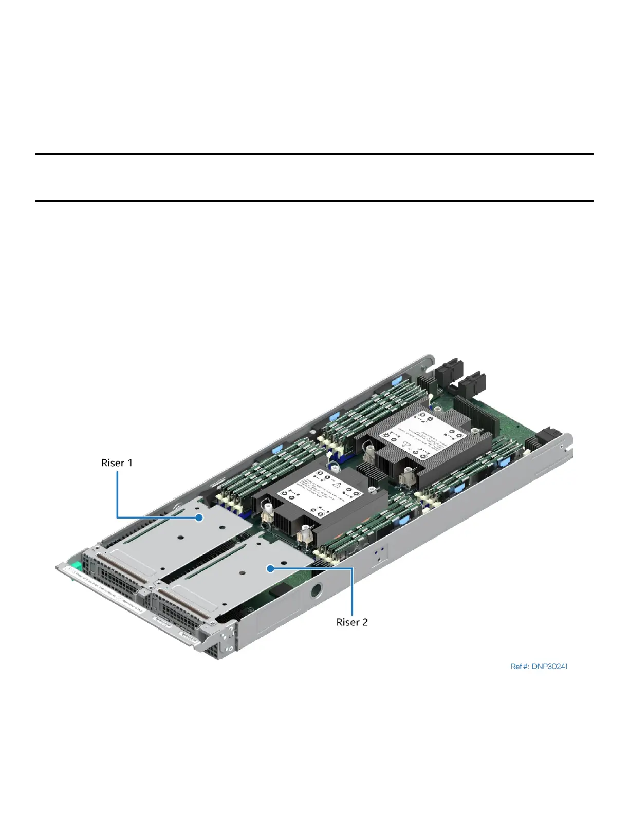
The 1U standard riser card goes in riser slot 2 on the server board while the 1U MCIO riser card goes in riser
slot 1. In addition, the MCIO connectors on the 1U MCIO riser card are cabled to the MCIO connector on the
server board. The riser assemblies have a label that indicates which riser slot they can go into.
Figure 65. Riser 1 and Riser 2 in 1U Compute Module
Each of the two 1U riser cards supports a single x16 PCIe* 5.0 add-in card slot (x16 electrical, x16
mechanical), compatible with low-profile PCIe* add-in cards. Each 1U riser card also includes support for a
single 80/110-mm PCIe* or SATA M.2 SSD storage device.