Intel® Server D50DNP Family Integration and Service Guide
127
7.3.2.3 PHM Reassembly
To properly reassemble the PHM and install it onto the server board, the procedures described in the
following sections must be followed in the order specified. These instructions assume that the processor
heat sink (new or reuse of existing) has the necessary thermal interface material (TIM) Honeywell PTM7000*
already applied to the clean bottom of the heat sink.
Caution: Full ESD precautions should be followed to perform assembly and installation of the PHM to the
server board. Wear ESD gloves to prevent electrostatic damage and oxidation or foreign materials on
processor package and land pads.
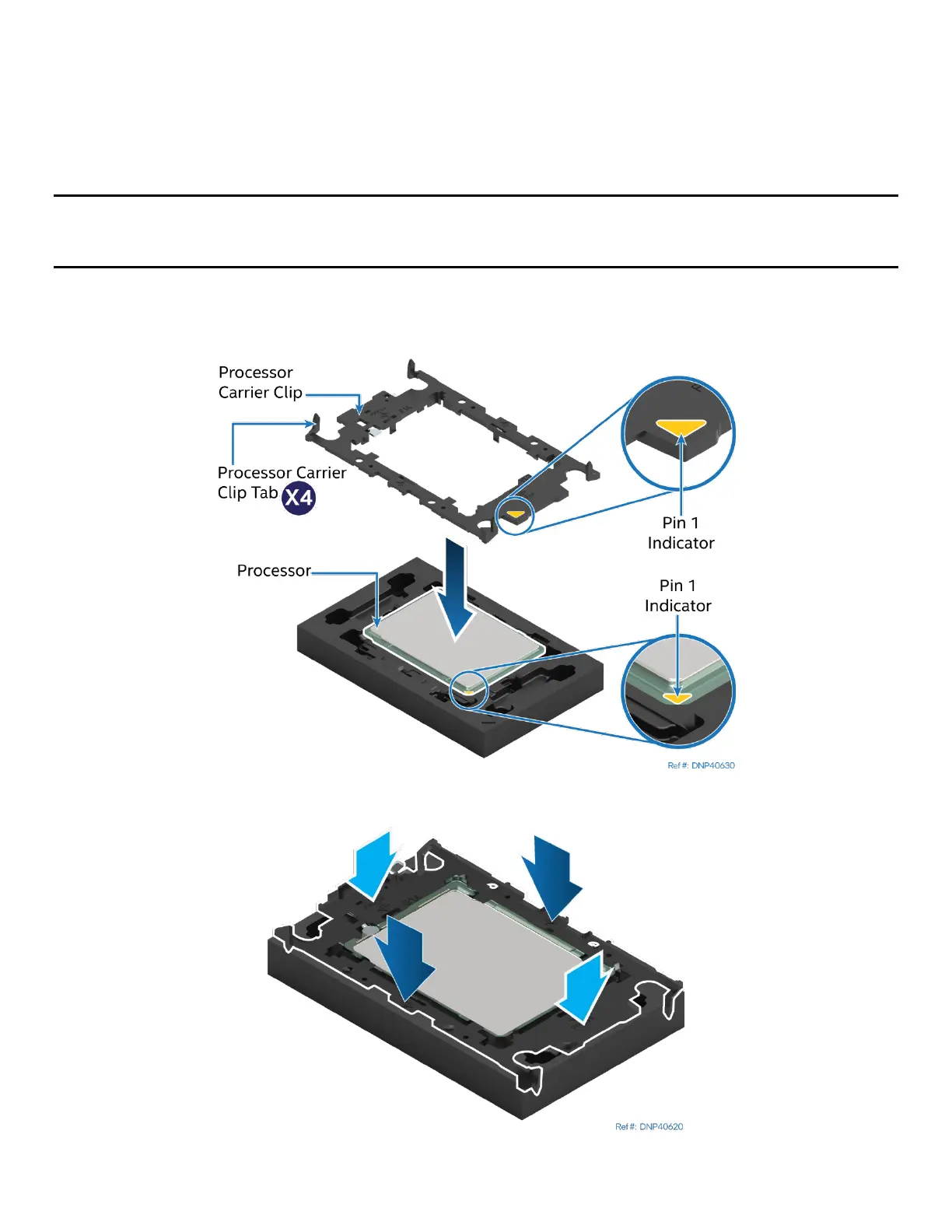
Each component within the PHM assembly includes a Pin 1 indicator. Pin 1 indicator alignment between all
components is required throughout the assembly process.
Figure 152. Installing Processor Carrier Clip onto Processor – Part 1
Figure 153. Installing Processor Carrier Clip onto Processor – Part 2