Intel® Server D50DNP Family Integration and Service Guide
29
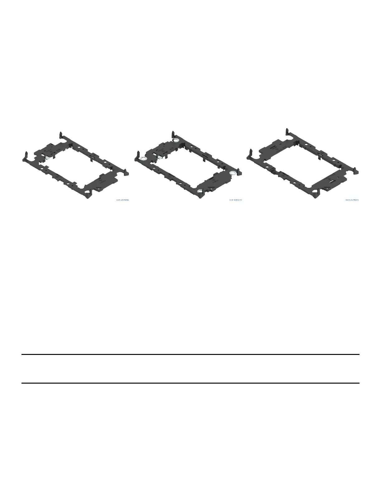
2.2.2 Processor Carrier Clips
Two carrier clips are available for the 4
th
Gen Intel® Xeon® Scalable processor family and one for Intel® Xeon®
CPU Max Series processors (see following figure). The choice of carrier clip depends on the processor type.
• 4
th
Gen Intel® Xeon® Scalable processor family XCC models use the E1A carrier clip.
• 4
th
Gen Intel® Xeon® Scalable processor family MCC models use the E1B carrier clip.
• Intel® Xeon® CPU Max Series processors family models use the E1C carrier clip.
The carrier clip designation (E1A, E1B, or E1C) is marked on each carrier clip. The designation for the needed
carrier clip is also marked on each processor package. The heat sinks for the Intel® D50DNP Modules support
all three carrier clips.
E1A Processor Carrier Clip E1B Processor Carrier Clip E1C Processor Carrier Clip
Figure 10. Supported Processor Carrier Clips
2.2.3 Assembly and Installation for Standard Air-Cooled Heat Sinks
Components Required
• 4
th
Gen Intel® Xeon® Scalable processors in shipping tray
• Processor carrier clips matching processor type
• 1U processor heat sinks (front and back) or 2U processor heat sinks (front and back)
Required Tools and Supplies
• Anti-static wrist strap and conductive workbench pad (recommended)
• Adjustable torque T30 Torx* screwdriver
• ESD gloves
Note: T
he installation figures in this section only display the 1U front heat sink and processor carrier clip
E1A. However, the processor installation procedure is the same, regardless of the size of the heat sink and
type of processor carrier clip.
A processor heat sink module (PHM) assembly and processor socket assembly (or “loading mechanism”) are
necessary to install a processor onto the server board. Figure 11 identifies each component associated with
the PHM and processor socket assemblies.