Intel® Server D50DNP Family Integration and Service Guide
142
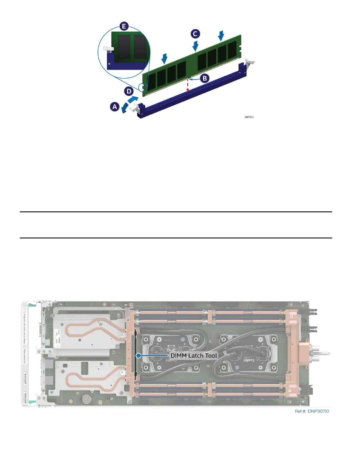
Figure 180. Installing the Memory Module in an Air-Cooled System
4. Ensure that the ejection tabs at both ends of the memory slot are in the open position (see Letter A).
5. Carefully unpack the replacement memory module, taking care to only handle the device by its outer
edges.
6. Align the notch at the bottom edge of the memory module with the key in the memory slot
(see Letter B).
7. Using even pressure along the top edge, push down on the memory module (see Letter C) until the
ejection tabs of the memory slot snap into place (see Letter D).
8. Ensure that the ejection tabs are firmly in place (see Letter E).
Note: Replacing Intel® Optane™ PMem devices requires additional steps to enable and configure them. Refer
to the appropriate Intel® Optane™ PMem documentation to complete the installation process for these
devices.
7.4.2 Memory Replacement for Liquid-Cooled Modules
Required Tools and Supplies:
• Anti-static wrist strap and conductive workbench pad (recommended)
• DIMM latch tool (attached to the cooling loop)
• Memory cooling kit (included in the liquid-cooling loop box) or DIMM PMIC spare kit (DNPLCDMTM)
Figure 181. DIMM Latch Tool Location