Intel® Server D50DNP Family Integration and Service Guide
130
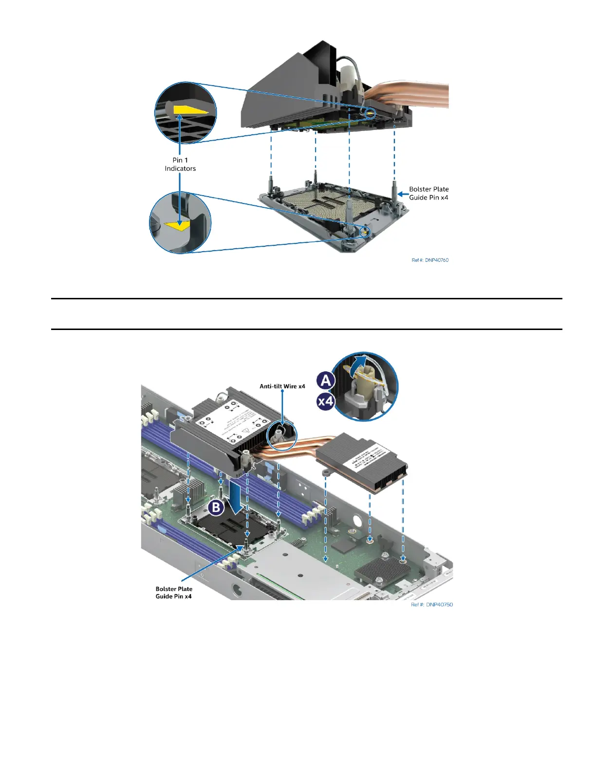
Figure 158. PHM Alignment with Socket Assembly
Caution: Processor socket pins are delicate and bend easily. Use extreme care when placing the PHM
onto the processor socket. Do not drop it.
Figure 159. PHM Installation onto Server Board
4. Set all four anti-tilt wires on the heat sink to the inward position (see Letter A).
5. Align the Pin 1 indicators of the processor carrier clip and processor with the Pin 1 indicator on the
socket assembly bolster plate.
6. Carefully lower the PHM over the four bolster plate alignment pins (see Letter B).