Intel® Server D50DNP Family Integration and Service Guide
79
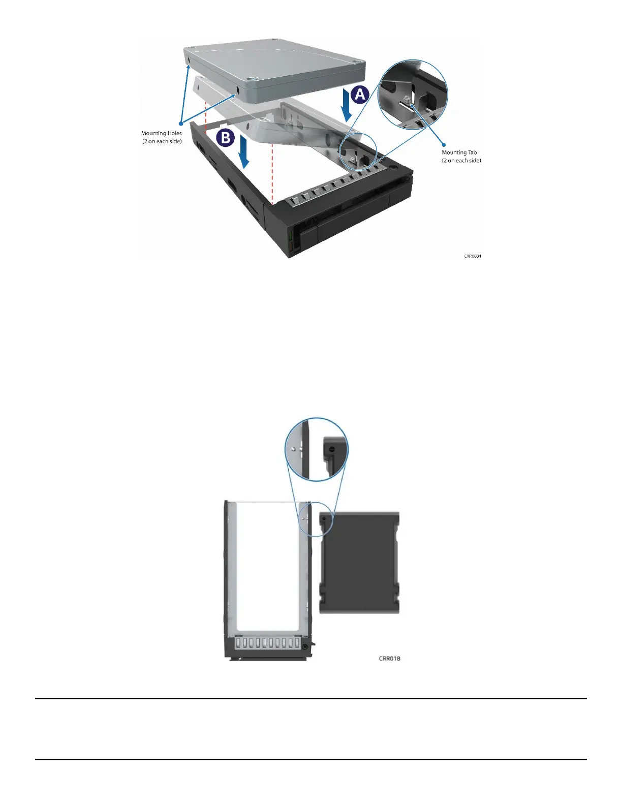
Figure 90. 2.5” Drive Installation into the Carrier
2. Carefully unpack the new drive, taking care not to touch any of the connector pins on the back side of
the drive.
3. Direct the drive edge connector toward the back of the drive carrier.
4. Position the mounting holes on one side of the drive over the mounting tabs on the drive carrier side
rail (see Letter A).
5. Lower the other side of the drive into the carrier (see Letter B) and press down on the drive until all
mounting tabs are locked in holes.
Figure 91. 2.5” Drive Carrier Alignment Features
Note: The 2.5” drive blank and drive carrier each have alignment features (see Figure 91
) ensuring proper
assembly. When reinstalling a drive blank into the drive carrier, ensure that the features are aligned before
installation. Failure to properly install a drive blank may result in the carrier assembly not fitting properly into
the drive bay.