Intel® Server D50DNP Family Integration and Service Guide
34
Caution: If debris is observed, blow it away gently with an air blower. Do not use tweezers or any
other hard tools to remove the debris.
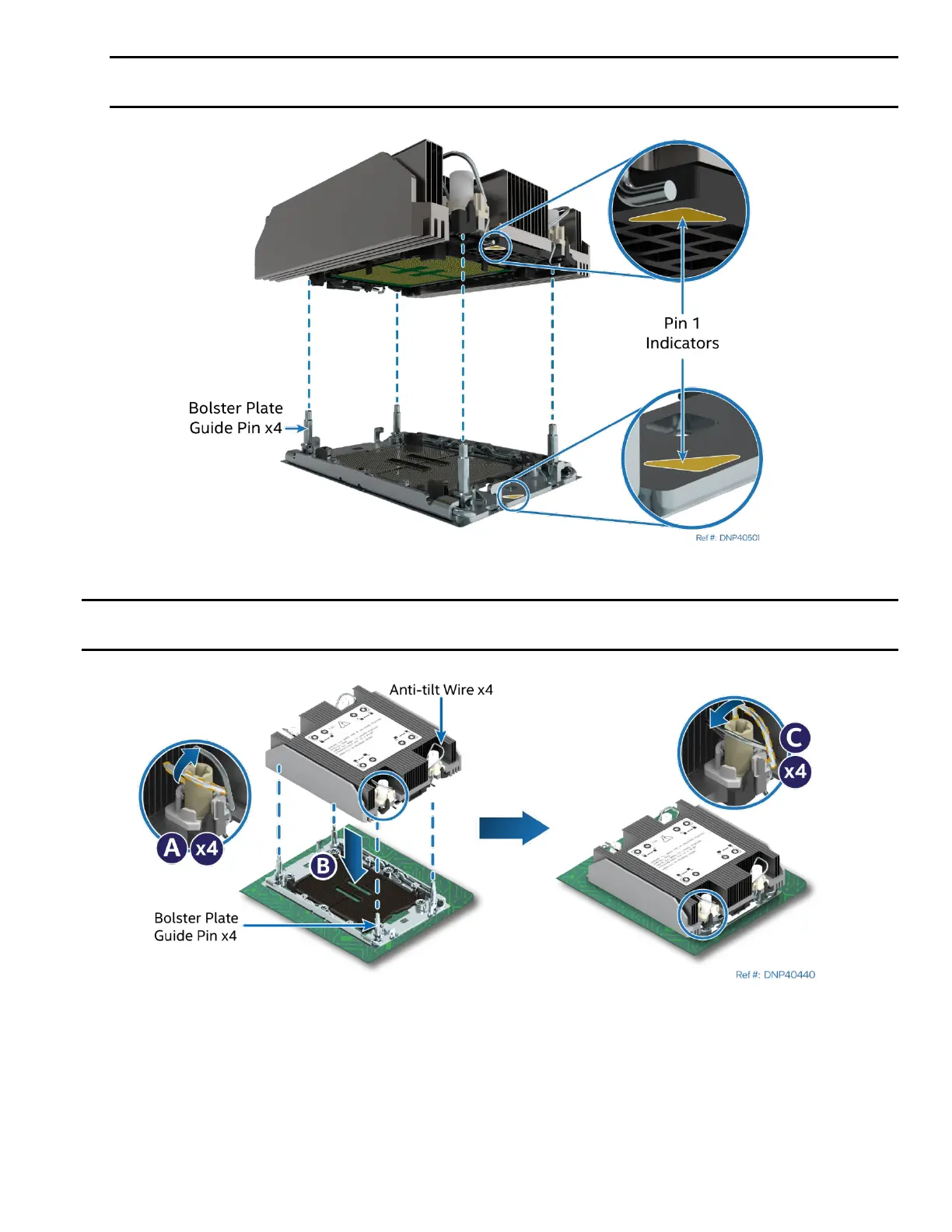
Figure 18. PHM Alignment with the Socket Assembly
Caution: Processor socket pins are delicate and bend easily. Use extreme care when placing the PHM
onto the processor socket. Do not drop it.
Figure 19. PHM Installation onto the Server Board
3. Set all four anti-tilt wires on the heat sink to the inward position (see Letter A).
4. Align the Pin 1 indicators of the processor carrier clip and processor with the Pin 1 indicator on the
socket assembly bolster plate.
5. Carefully lower the PHM over the four bolster plate alignment pins (see Letter B).
6. Ensure that the PHM is sitting flat and even on the bolster plate.
7. Set all four anti-tilt wires on the heat sink to the outward position (see Letter C).