Intel® Server D50DNP Family Integration and Service Guide
37
2.2.4.1 Processor Heat Sink Module (PHM) Assembly
Caution: Full ESD precautions should be followed to perform assembly and installation of the PHM to the
server board. Wear ESD gloves to prevent electrostatic damage and oxidation or foreign materials on
processor package and land pads.
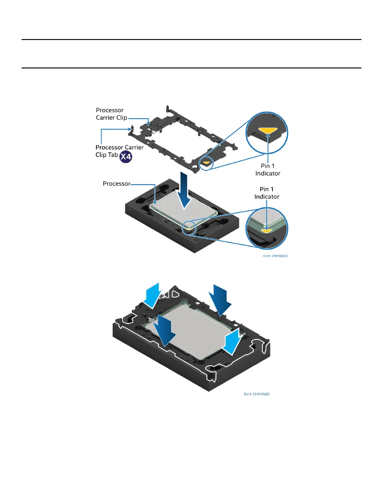
Each component within the PHM assembly includes a Pin 1 indicator. Pin 1 indicator alignment between all
components is required throughout the assembly process.
Figure 22. Installing the Processor Carrier Clip onto the Processor – Part 1
Figure 23. Installing the Processor Carrier Clip onto the Processor – Part 2
1. Align the Pin 1 indicator on the processor carrier clip with the Pin 1 indicator of the processor.
2. With the processor still in its tray, place the processor carrier clip over the processor.
3. Gently press down simultaneously on two opposite sides of the processor carrier clip until it clicks in
place.
4. Repeat step 3 for the other two sides.