Intel® Server D50DNP Family Integration and Service Guide
54
Figure 50. Attaching Thermal Pad to DIMM PMIC
3. Carefully detach one PMIC thermal pad from the paper and attach it to the DIMM power management
integrated circuit (PMIC) as show on the previous picture.
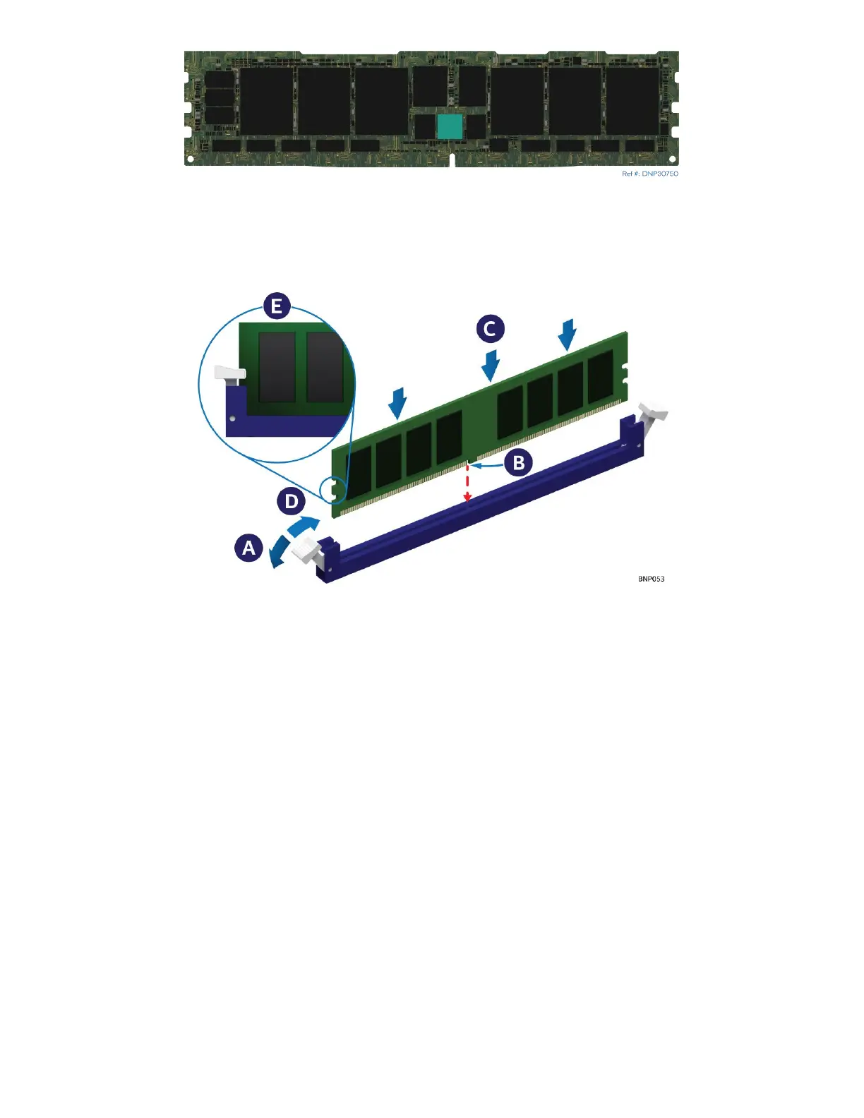
Figure 51. Installing DIMM for Liquid-Cooled Module
4. Using the DIMM latch tool push on the memory slot ejection tabs one-by-one to move them to the
open position (see Letter A). Make sure that the TIM pads covering memory heat spreader line do not
interfere with the memory slot.
5. Align the notch at the bottom edge of the memory module with the key in the memory slot
(see Letter B).
6. Insert the memory module into the memory slot
7. Using even pressure along the top edge, push down on the memory module (see Letter C) until the
ejection tabs of the memory slot snap into place (see Letter D).
8. Ensure that the ejection tabs are firmly in place (see Letter E).
9. Repeat steps 2 through 8 for all other DIMMs.
10. Attach the DIMM latch tool to the cooling loop