4200-900-01 Rev. K / February 2017 Return to Section Topics 3-111
Model 4200-SCS User’s Manual Section 3: Common Device Characterization Tests
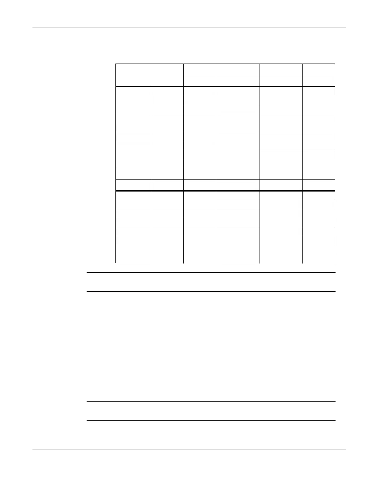
Table 3-28
Segment ARB parameter values for example waveforms
NOTE HEOR – The solid state relay (SSR) on the output of each pulse channel, which
provides a high impedance disconnect.
Entering Segment ARB values into UTM array parameters
The second method for defining a Segment ARB
®
waveform is by entering
values into arrays for the UTM tests:
• Program
•Erase
• Fast-Program-Erase
These UTM-based Segment ARB waveforms have been partially pre-defined to
reduce the number of parameters required. Figure 3-102 defines the parameters
for the single pulse Program and Erase waveforms.
NOTE The sign of the PulseVoltages array determines whether the pulse is positive (usually
for a Program pulse) or negative (usually for an Erase pulse).
PMU1 Channel 1
Segment Start V Stop V Time (s) Trigger HEOR*
1 0 8 20.00 E-8 1 1
2 8 8 50.00 E-4 0 1
3 8 0 20.00 E-8 0 1
4 0 0 10.00 E-4 0 1
5 0 -7 20.00 E-8 1 1
6 -7-75.00 E-20 1
7 -7 0 20.00 E-8 0 1
8 0 0 20.00 E-8 0 1
PMU Channel 2
Segment Start V Stop V Time (s) Trigger HEOR*
1 0 0 20.00 E-8 1 1
2 0 0 50.00 E-4 0 1
3 0 0 20.00 E-8 0 1
4 0 0 10.00 E-4 0 1
5 0 -5 20.00 E-8 1 1
6 -5-55.00 E-20 1
7 -5 0 20.00 E-8 0 1
8 0 0 20.00 E-8 0 1

 Loading...