Repair Information 4-11
4023-001
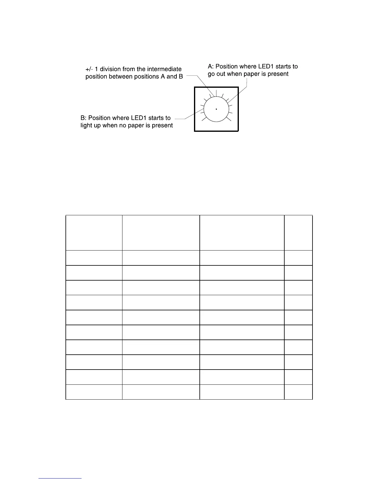
4. Adjust VR to the intermediate position between positions A and
B (must be within +/−1 division from the intermediate position)
Paper Empty Detecting Sensor Adjustment
Perform this adjustment when the circuit board for the paper empty
detecting sensor is replaced.
Note: The specified paper must be used for adjustment. The VR
must be turned in the correct direction as described.
1. Rotate VR to the full-clockwise position and turn the printer ON.
2. Start test mode and set the sensor input mode. See “Sensor
Input Check ()” on page 3-30.
(a)
Replaced
Component
(b)
Sensor
(c)
Test Mode Sensor
Input Check
(d)
VR
PWB-D1 1-Bin Empty Sensor Group 3, LED1 VR1
PWB-D2 2-Bin Empty Sensor Group 3, LED2 VR2
PWB-D3 3-Bin Empty Sensor Group 3, LED3 VR3
PWB-D4 4-Bin Empty Sensor Group 3, LED4 VR4
PWB-D5 5-Bin Empty Sensor Group 3, LED5 VR5
PWB-D6 6-Bin Empty Sensor Group 4, LED1 VR6
PWB-D7 7-Bin Empty Sensor Group 4, LED2 VR7
PWB-D8 8-Bin Empty Sensor Group 4, LED3 VR8
PWB-D9 9-Bin Empty Sensor Group 4, LED4 VR9
PWB-C 10-Bin Empty Sensor Group 4, LED5 VR10