215184 131 Revision A
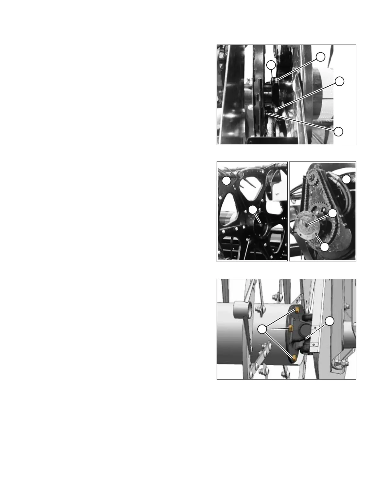
Figure 3.278: Reel at Right Arm
8. Secure reel at right arm with four 1/2 x 1-1/4 in. long hex
bolts (A) and lock washers from hardware bag B. Apply
medium-strength threadlocker (Loctite
®
243 or equivalent)
onto bolt before assembly. Torque bolts to 108 Nm
(80 lbf·ft).
Figure 3.279: Reel Stub Shaft and U-Joint Flange Hole
9. Position the tail end of right reel (A) against the U-joint
flange of left reel (B).
10. Engage reel stub shaft (C) into U-joint flange hole (D).
11. Rotate reel so tine tubes are either aligned or staggered
relative to the existing reel. Align holes (E) in U-joint flange
with holes in center tube at either position.
NOTE:
Staggering tine tubes balances the load on reel and reel
drive, especially in heavy crops.
Figure 3.280: Reel and U-Joint
12. Install four 1/2 x 1-1/4 in. long hex bolts with lock
washers (A) (from the hardware bag labelled B) to connect
reel to the U-joint. Apply medium-strength threadlocker
(Loctite
®
243 or equivalent) to bolt before assembly.
Torque bolts to 108 Nm (80 lbf·ft).
13. Remove sling from reel.
ASSEMBLING THE HEADER AND FLOAT MODULE