215184 134 Revision A
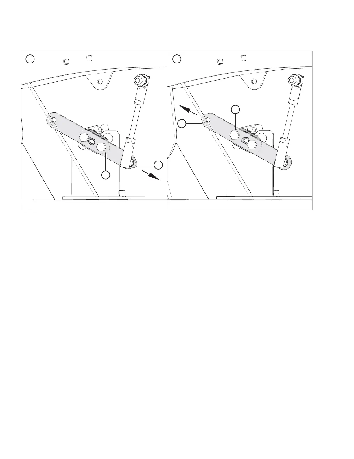
Figure 3.285: Sensor Arm/Pointer Configurations
A - Case/New Holland Configuration B - John Deere/CLAAS/AGCO IDEAL
™™
Configuration
C - Sensor Arm (Shown Semitransparent) D - Sensor Pointer (Shown Under Sensor Arm)
NOTE:
• For configuration (A), pointer (D) points to the FRONT of the header.
• For configuration (B), pointer (D) points to the REAR of the header.
• Sensor arm made semitransparent to show sensor pointer behind it.
2. Check that sensor arm (C) and pointer (D) are configured properly for your combine. For instructions, refer to Figure
3.285, page 134.
ASSEMBLING THE HEADER AND FLOAT MODULE