215184 193 Revision A
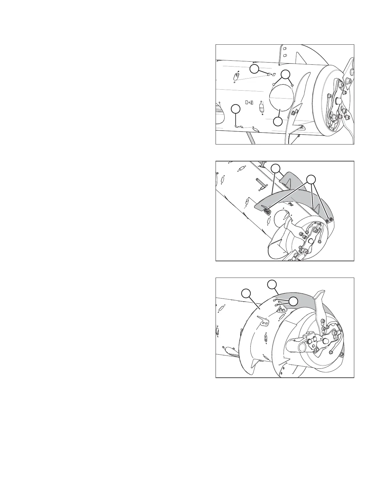
Figure 6.41: Wide Configuration – Right Side
6. Converting from Wide configuration: Remove bolts (A),
access cover (B), and two flighting slot plugs (C) from the
right side of the auger.
7. Repeat Steps 2, page 192 to 6, page 193 at the left side of
the auger.
Figure 6.42: Right Side of Auger
8. Position two bolt-on flightings (A) on the right side, as
shown. Temporarily secure flightings with two carriage
head bolts and nuts at each location (B).
Figure 6.43: Right Side of Auger
9. Position another bolt-on flighting (A) outboard of the
temporarily installed bolt-on flighting (B). Mark hole
locations (C) of the bolt-on flighting onto the temporarily
installed bolt-on flighting (B).
10. Remove temporarily installed bolt-on flighting (B) from the
auger and drill two 11 mm (7/16 in.) holes at the marked
locations.
11. Install bolt-on flighting (B) with newly drilled holes using six
carriage head bolts and nuts.
IMPORTANT:
Carriage bolt heads must be installed on the inside of the
auger to prevent damaging internal components.
12. Repeat Step 9, page 193 to Step 11, page 193 to the
remaining bolt-on flighting on the right side of the auger.
FLOAT MODULE SETUP AT DEALER