215184 274 Revision A
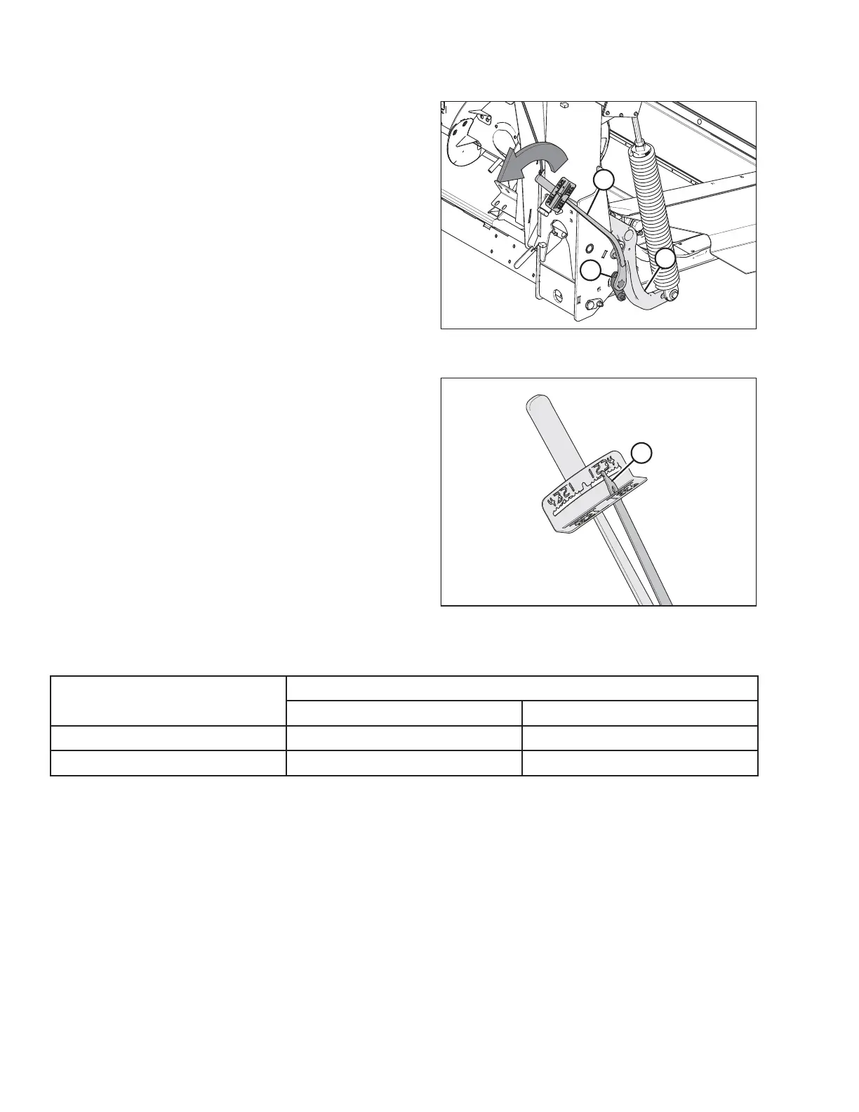
Figure 8.26: Float Module – Right Side
Figure 8.27: Torque Wrench
13. Push down on the wrench until indicator (A) reaches a
maximum reading and then begins to decrease. Note the
maximum reading. Repeat at opposite side.
14. Use the following table as a guide for float settings:
• If reading on the wrench is high, the header is heavy
• If reading on the wrench is low, the header is light
Table 8.2 Float Settings
Header Size
Indicator Reading
Cutting on the Ground Cutting off the Ground
D120, D125, D130, and D135
1 1/2 to 2 2 to 2 1/2
D140 and D145
2 to 2 1/2 2 1/2 to 3
PERFORMING PREDELIVERY CHECKS