215184 301 Revision A
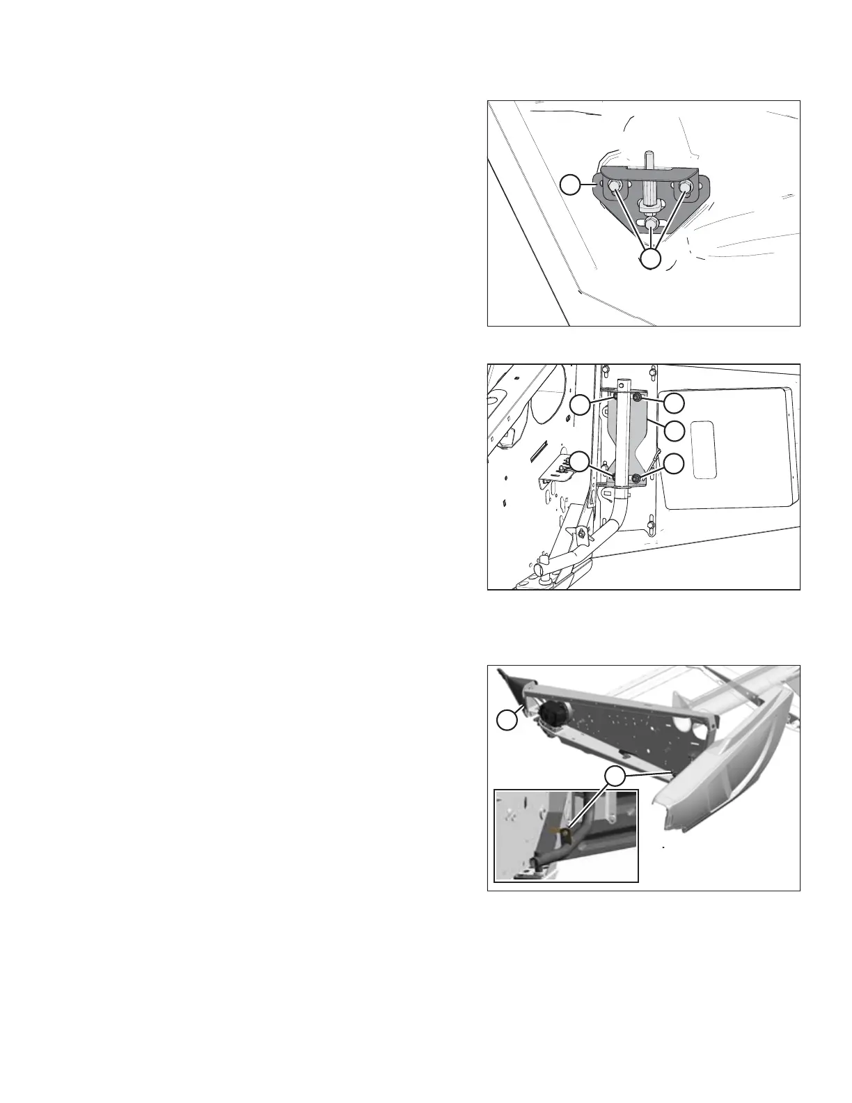
Figure 8.73: Left Endshield Latch Assembly
2. Loosen three bolts (A) on latch assembly (B).
3. Adjust latch assembly (B) to achieve the desired gap
between the front end of the shield and the header frame.
Refer to Table 8.5, page 299 for the recommended
endshield gap at various temperatures.
4. Tighten three bolts (A) on the latch assembly to 27 Nm
(20 lbf·ft).
Figure 8.74: Left Endshield Support Tube
5. Tighten four bolts (A) on support tube bracket (B) to 31 Nm
(23 lbf·ft).
Closing the endshield:
Figure 8.75: Left Endshield
1. Disengage lock (B) to allow endshield to move.
2. Insert front of endshield behind hinge tab (A) and into
divider cone.
PERFORMING PREDELIVERY CHECKS