5.2 European Standards
156 SIEPCYEUOQ2V01A Q2V Technical Manual
Model Terminal
Recommended Gauge
mm
2
Applicable Gauge
mm
2
Wire Stripping
Length
*1
mm
Terminal Screw
Tightening Torque
N∙m (in∙lb)
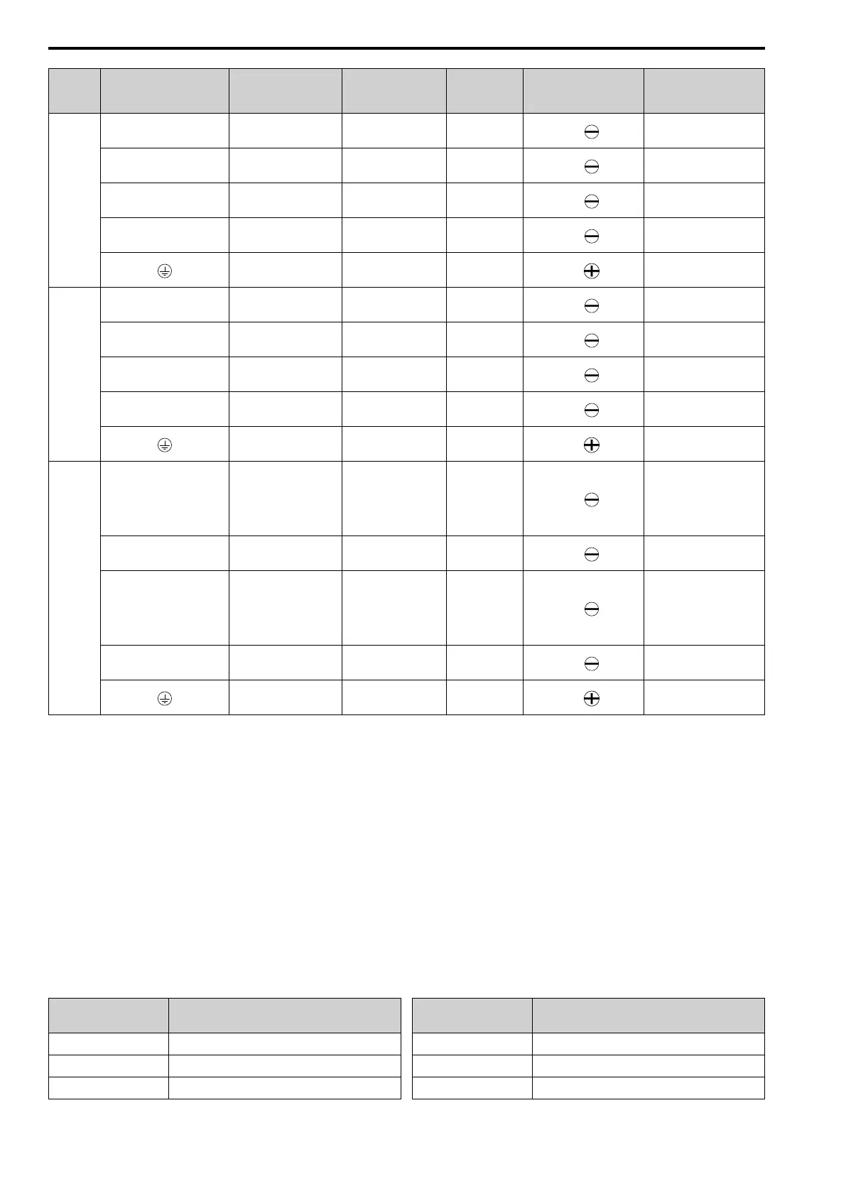
4038
R/L1, S/L2, T/L3 10 4 - 16 10
M4
1.5 - 1.7
(13.5 - 15)
U/T1, V/T2, W/T3 6 2.5 - 10 10
M4
1.5 - 1.7
(13.5 - 15)
-, +1, +2 16 4 - 25 18
M5
2.3 - 2.5
(19.8 - 22)
B1, B2 4 2.5 - 6 10
M4
1.5 - 1.7
(13.5 - 15)
10 6 - 16 -
M6
5.4 - 6.0
(47.8 - 53.1)
4044
R/L1, S/L2, T/L3 16 4 - 25 18
M5
2.3 - 2.5
(19.8 - 22)
U/T1, V/T2, W/T3 10 4 - 16 18
M5
2.3 - 2.5
(19.8 - 22)
-, +1, +2 16 6 - 25 18
M5
2.3 - 2.5
(19.8 - 22)
B1, B2 6 4 - 10 10
M4
1.5 - 1.7
(13.5 - 15)
10 6 - 16 -
M6
5.4 - 6.0
(47.8 - 53.1)
4060
R/L1, S/L2, T/L3 25 6 - 35 18
M5
• ≤ 25 mm
2
2.3 - 2.5
(19.8 - 22)
• 35 mm
2
≤
4.1 - 4.5
(36 - 40)
U/T1, V/T2, W/T3 16 4 - 25 18
M5
2.3 - 2.5
(19.8 - 22)
-, +1, +2 25 6 - 35 18
M5
• ≤ 25 mm
2
2.3 - 2.5
(19.8 - 22)
• 35 mm
2
≤
4.1 - 4.5
(36 - 40)
B1, B2 10 2.5 - 16 10
M4
1.5 - 1.7
(13.5 - 15)
10 6 - 16 -
M6
5.4 - 6.0
(47.8 - 53.1)
*1 Remove insulation from the ends of wires to expose the length of wire shown.
*2 If you turn on the internal EMC filter, the leakage current of the drive will be more than 3.5 mA. Use these closed-loop crimp
terminals or equivalent to connect a protective ground wire that has a minimum cross-sectional area of 10 mm
2
(copper wire).
• 8-4NS from JST Mfg. Co., Ltd.
• R8-4S from NICHIFU Co.,Ltd.
■ Connect a Fuse to the Input Side (Primary Side)
The drive circuit protection must comply with EN 61800-5-1:2007 for protection against a short circuit in the
internal circuitry. Connect semiconductor protection fuses on the input side for branch circuit protection.
WARNING! Electrical Shock Hazard. After the drive blows a fuse or trips an RCM/RCD, do not immediately energize the drive
or operate peripheral devices. Wait for the time specified on the warning label at a minimum and make sure that all indicators
are OFF. Then check the wiring and peripheral device ratings to find the cause of the problem. If you do not know the cause of
the problem, contact the manufacturer before you energize the drive or peripheral devices. If you do not fix the problem before
you operate the drive or peripheral devices, it can cause serious injury or death.
Three-Phase 200 V Class
Table 5.2 Factory-Recommended Branch Circuit Protection: Three-Phase 200 V Class
Drive Model
Semiconductor Protection Fuse Rated Current
Manufacturer: EATON/Bussmann
2001 FWH-25A14F
2002 FWH-25A14F
2004 FWH-25A14F
Drive Model
Semiconductor Protection Fuse Rated Current
Manufacturer: EATON/Bussmann
2006 FWH-25A14F
2008 FWH-70B
2010 FWH-70B

 Loading...


