5.3 UL Standards
168 SIEPCYEUOQ2V01A Q2V Technical Manual
WARNING! Electrical Shock Hazard. Make sure that the protective ground wire conforms to technical standards and local
safety regulations. The IEC/EN 61800-5-1:2007 standard specifies that you must wire the power supply to automatically de-
energize when the protective ground wire disconnects. If you turn on the internal EMC filter, the leakage current of the drive will
be more than 3.5 mA. You can also connect a protective ground wire that has a minimum cross-sectional area of 10 mm
2
(copper wire). If you do not obey the standards and regulations, it can cause serious injury or death.
WARNING! Electrical Shock Hazard. Only connect peripheral options, for example a DC reactor or braking resistor, to terminals
+1, +2, -, B1, and B2. Failure to obey can cause serious injury or death.
Note:
• The recommended wire gauges are based on drive continuous current ratings with 75 °C (167 °F) 600 V class 2 heat-resistant indoor
PVC wire. Assume these conditions:
–Ambient temperature: 40 °C (104 °F) maximum
–Wiring distance: 100 m (3281 ft) maximum
–Normal Duty rated current value
• Refer to the instruction manual for each device for recommended wire gauges to connect peripheral devices or options to terminals +1,
+2, -, B1, and B2. Contact the manufacturer or your nearest sales representative if the recommended wire gauges for the peripheral
devices or options are out of the range of the applicable gauges for the drive.
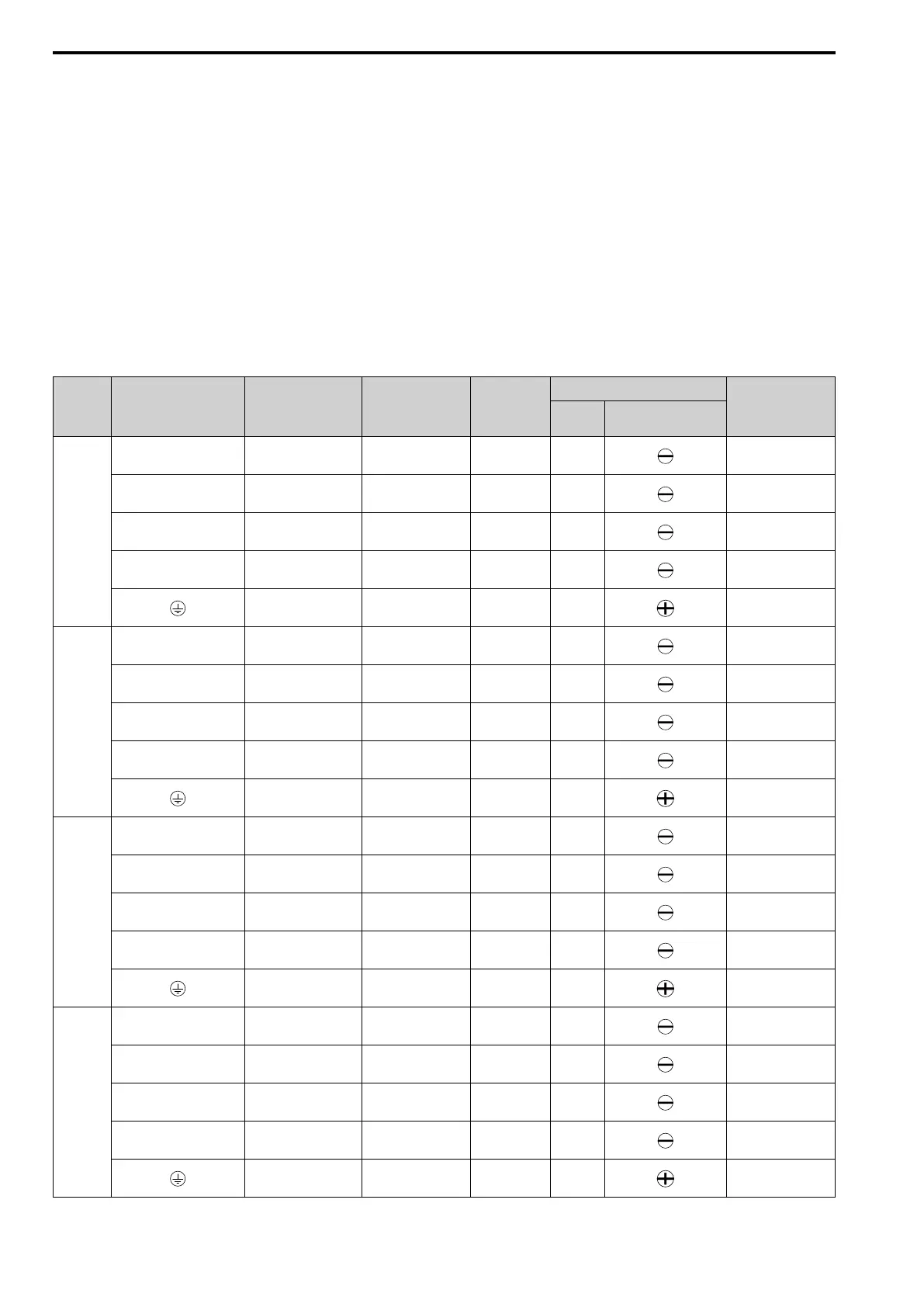
Three-Phase 200 V Class (UL Compliance)
Model Terminal
Recommended
Gauge
AWG, kcmil
Applicable Gauge
AWG, kcmil
Wire
Stripping
Length
*1
mm
Terminal Screw
Tightening Torque
N∙m (in∙lb)
Size Shape
2001
R/L1, S/L2, T/L3 14 14 6.5 M3
0.5 - 0.6
(4.4 - 5.3)
U/T1, V/T2, W/T3 14 14 6.5 M3
0.5 - 0.6
(4.4 - 5.3)
-, +1, +2 14 14 6.5 M3
0.5 - 0.6
(4.4 - 5.3)
B1, B2 14 14 6.5 M3
0.5 - 0.6
(4.4 - 5.3)
14
*2
14
*2
- M3.5
0.8 - 1.0
(7.1 - 8.9)
2002
R/L1, S/L2, T/L3 14 14 6.5 M3
0.5 - 0.6
(4.4 - 5.3)
U/T1, V/T2, W/T3 14 14 6.5 M3
0.5 - 0.6
(4.4 - 5.3)
-, +1, +2 14 14 6.5 M3
0.5 - 0.6
(4.4 - 5.3)
B1, B2 14 14 6.5 M3
0.5 - 0.6
(4.4 - 5.3)
14
*2
14
*2
- M3.5
0.8 - 1.0
(7.1 - 8.9)
2004
R/L1, S/L2, T/L3 14 14 6.5 M3
0.5 - 0.6
(4.4 - 5.3)
U/T1, V/T2, W/T3 14 14 6.5 M3
0.5 - 0.6
(4.4 - 5.3)
-, +1, +2 14 14 6.5 M3
0.5 - 0.6
(4.4 - 5.3)
B1, B2 14 14 6.5 M3
0.5 - 0.6
(4.4 - 5.3)
14
*2
14
*2
- M3.5
0.8 - 1.0
(7.1 - 8.9)
2006
R/L1, S/L2, T/L3 14 14 6.5 M3
0.5 - 0.6
(4.4 - 5.3)
U/T1, V/T2, W/T3 14 14 6.5 M3
0.5 - 0.6
(4.4 - 5.3)
-, +1, +2 14 14 6.5 M3
0.5 - 0.6
(4.4 - 5.3)
B1, B2 14 14 6.5 M3
0.5 - 0.6
(4.4 - 5.3)
14
*2
14
*2
- M3.5
0.8 - 1.0
(7.1 - 8.9)

 Loading...


