6.3 Modbus Communications
204 SIEPCYEUOQ2V01A Q2V Technical Manual
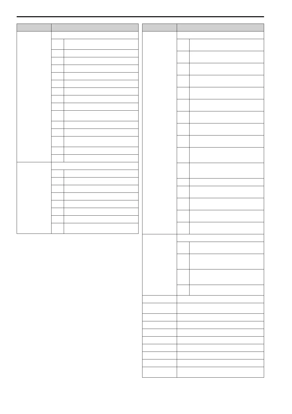
Register No. (Hex.) Description
002A
Minor Fault Description 1
bit 0 -
1
Reserved
bit 2 EF [FWD/REV Run Command Input Error]
bit 3 bb [Baseblock]
bit 4 oL3 [Overtorque 1]
bit 5 oH [Heatsink Overheat]
bit 6 ov [Overvoltage]
bit 7 Uv [Undervoltage]
bit 8 Reserved
bit 9 CE [Modbus Communication Error]
bit
A
bUS [Option Communication Error]
bit B UL3/UL4 [Undertorque Detection 1/2]
bit C oH3 [Motor Overheat (PTC Input)]
bit D
FbL [PID Feedback Loss], FbH [Excessive PID
Feedback]
bit E Reserved
bit F CALL [Serial Comm Transmission Error]
002B
U1-10 [In Terminal Status]
bit 0 1: Control circuit terminal DI1 ON
bit 1 1: Control circuit terminal DI2 ON
bit 2 1: Control circuit terminal DI3 ON
bit 3 1: Control circuit terminal DI4 ON
bit 4 1: Control circuit terminal DI5 ON
bit 5 1: Control circuit terminal DI6 ON
bit 6 1: Control circuit terminal DI7 ON
bit 7 -
F
Reserved
Register No. (Hex.) Description
002C
Drive Status 2
bit 0
During Run
1: During Run
bit 1
During zero speed
1: During zero speed
bit 2
Speed agreement
1: During agreement
bit 3
User-defined speed agreement
1: During agreement
bit 4
Frequency Detection 1
1: Output frequency ≤ L4-01
bit 5
Frequency Detection 2
1: Output frequency ≥ L4-01
bit 6
Drive ready
1: Run ready
bit 7
During low voltage detection
1: During detection
bit 8
During baseblock
1: Drive output during baseblock
bit 9
Frequency reference mode
1: No communication option, 0: Communication
option
bit A
Run command mode
1: No communication option, 0: Communication
option
bit B During overtorque/undertorque 1, 2 detection
bit C
Frequency reference loss
1: Loss
bit D
Executing Auto-Restart
1: Restart Enabled
bit E
Fault
1: Fault generated
bit F
Modbus communications timeout
1: At Timeout
002D
U1-11 [Output Terminal Status]
bit 0
MFDO (terminal NO/NC-CM)
1: ON, 0: OFF
bit 1
Multi-function photocoupler output 1 (terminal
DO1-O1C)
1: ON, 0: OFF
bit 2
Multi-function photocoupler output 2 (terminal
DO2-O2C)
1: ON, 0: OFF
bit 3 -
F
Reserved
002E Reserved
002F
Frequency reference bias (Up 2/Down 2 function) (Units:
0.1%)
0030 Reserved
0031 U1-07 [DC Bus Voltage] (unit: 1 V)
0032 U1-09 [Torque Reference] (unit: 1%)
0033 Reserved
0034 Product Code 1 (2-character ASCII code), Q2V = “0A”
0035 Product Code 2 (2-character ASCII code), Q2V = “52”
0036 - 0037 Reserved
0038
PID Feedback: Unsigned, input is equivalent to 100%/
maximum output frequency (Units:0.1%)

 Loading...


