Network Communications
6
6.3 Modbus Communications
SIEPCYEUOQ2V01A Q2V Technical Manual 203
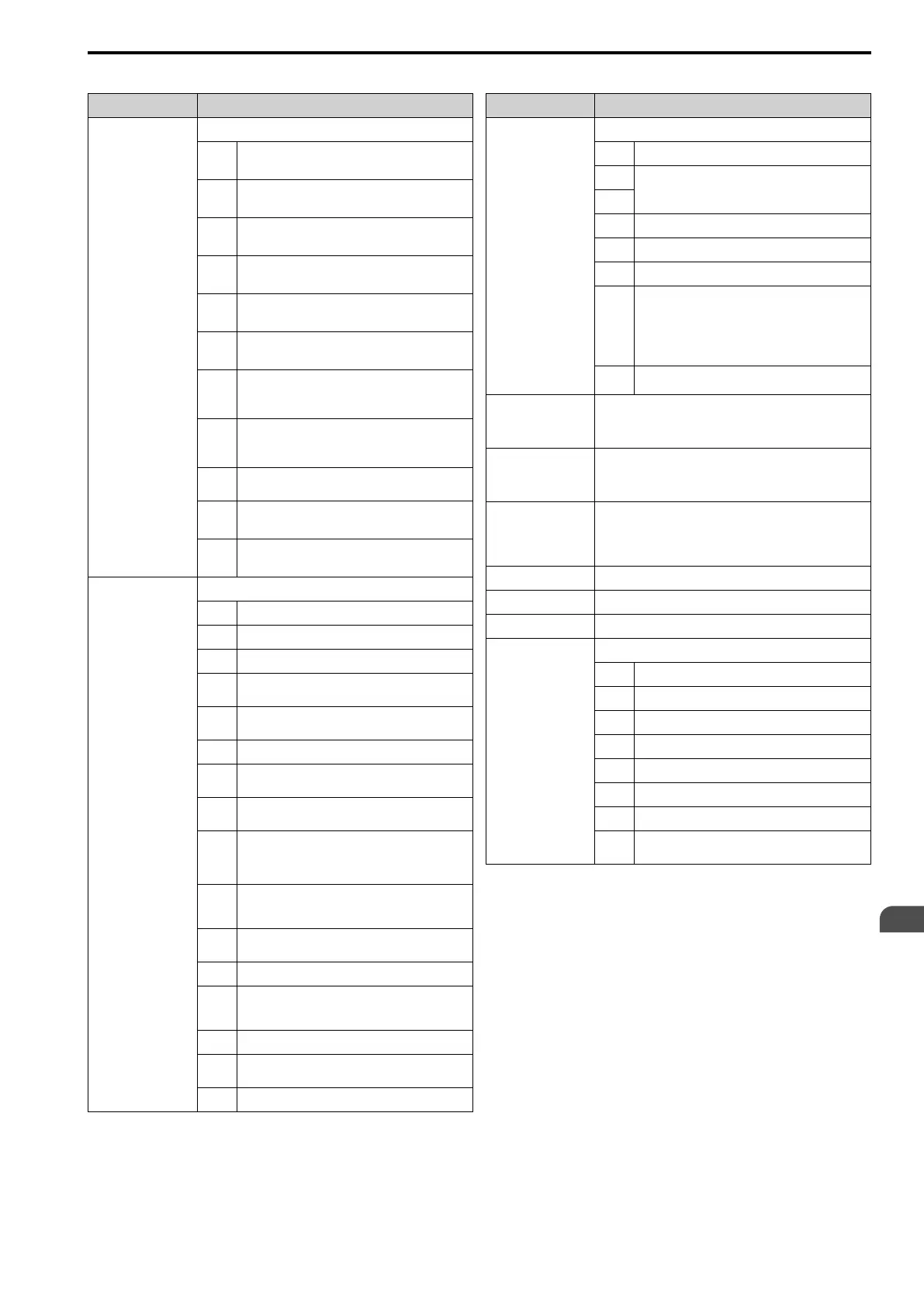
Table 6.11 Monitor Data for Modbus Communication
Register No. (Hex.) Description
0020
Drive Status 1
bit 0
During Run
1: During run, 0: During stop
bit 1
During reverse
1: During reverse, 0: Forward run
bit 2
Drive ready
1: Ready, 0: Not ready
bit 3
Fault
1: Fault
bit 4
Data Setting Error
1: oPExx error
bit 5
MFDO (terminal NO/NC-CM)
1: ON, 0: OFF
bit 6
Multi-function photocoupler output 1 (terminal
DO1-O1C)
1: ON, 0: OFF
bit 7
Multi-function photocoupler output 2 (terminal
DO2-O2C)
1: ON, 0: OFF
bit 8 -
D
Reserved
bit E
ComRef status
1: Enabled
bit F
ComCtrl status
1: Enabled
0021
Fault Description 1
bit 0 oC [Overcurrent], GF [Ground Fault]
bit 1 ov [Overvoltage]
bit 2 oL2 [Drive Overload]
bit 3
oH1 [Heatsink Overheat], oH2 [External Overheat
(H1-XX=7D)]
bit 4
rH [Braking Resistor Overheat], rr [Dynamic
Braking Transistor Fault]
bit 5 Reserved
bit 6
FbL [PID Feedback Loss], FbH [Excessive PID
Feedback]
bit 7
EF0 [Option Card External Fault], EF1 to EF7
[External Fault]
bit 8
CPFxx [Hardware Fault]
Note:
Includes oFx.
bit 9
oL1 [Motor Overload], oL3, oL4 [Overtorque
Detection 1/2], UL3, UL4 [Undertorque Detection
1/2]
bit A
PGo [Encoder (PG) Feedback Loss], oS
[Overspeed], dEv [Speed Deviation]
bit B During Uv [Undervoltage] detection
bit C
Uv1 [DC Bus Undervoltage], Uv2 [Control Power
Undervoltage], Uv3 [Soft Charge Answerback
Fault]
bit D LF [Output Phase Loss], PF [Input Phase Loss]
bit E
CE [Modbus Communication Error], bUS [Option
Communication Error]
bit F Reserved
Register No. (Hex.) Description
0022
Fault Contents
bit 0 1: During data writing, during motor switching
bit 1
Reserved
bit 2
bit 3 1: Upper/Lower Limit Fault
bit 4 1: Data Integrity Fault
bit 5 1: During EEPROM writing
bit 6
0: EEPROM writing
1: Change data only on the RAM
Note:
Enabled when H5-17 = 2 [ENTER@CPU Busy
Response = Write RAM Only].
bit 7 -
F
Reserved
0023
U1-01 [Frequency Reference]
Note:
o1-03 [FrqDisplay Unit Selection] sets the units.
0024
U1-02 [Output Frequency]
Note:
o1-03 [Frequency Display Unit Selection] sets the units.
0025
U1-06 [Output Voltage Ref] (units: 0.1 V)
Note:
Use H5-10 [Mbus 0025H Unit Sel] to change the setting
unit.
0026
U1-03 [Output Current] (units: 0.1 A)
0027 U1-08 [Output Power]
0028 U1-09 [Torque Reference]
0029
Fault Description 2
bit 0 Reserved
bit 1 GF [Ground Fault]
bit 2 PF [Input Phase Loss]
bit 3 LF [Output Phase Loss]
bit 4 rH [Braking Resistor Overheat]
bit 5 Reserved
bit 6 oH4 [Motor Overheat Fault (PTC Input)]
bit 7 -
F
Reserved

 Loading...


