Parameter Details
12
12.2 b: APPLICATION
SIEPCYEUOQ2V01A Q2V Technical Manual 451
■ b1-14: Phase Order Selection
No.
(Hex.)
Name Description
Default
(Range)
b1-14
(01C3)
Phase Order Selection
Sets the phase order for output terminals U/T1, V/T2, and W/T3. This parameter can align the
Forward Run command from the drive and the forward direction of the motor without changing
wiring.
0
(0, 1)
0 : Standard
1 : Phase Order Switch
■ b1-15: Freq. Ref. Sel. 2
No.
(Hex.)
Name Description
Default
(Range)
b1-15
(01C4)
Freq. Ref. Sel. 2
Sets the input method for frequency reference 2.
0
(0 - 4)
This parameter is enabled when H1-xx = 9 [MFDI Function Select = Ext Ref 1/2] is activated.
Note:
• Push on the keypad to set the input mode to LOCAL and use the keypad to enter the frequency reference.
• If the frequency reference is 0 Hz or less than or equal to the value set in E1-09 [Min Output Frequency] and the drive receives the Run
command, the RUN LED on the keypad will flash. Examine the setting for the frequency reference input and enter a value more than
or equal to E1-09.
0 : Keypad
Use the keypad to enter the frequency reference.
Use and on the keypad to change the frequency reference.
1 : Analog Input
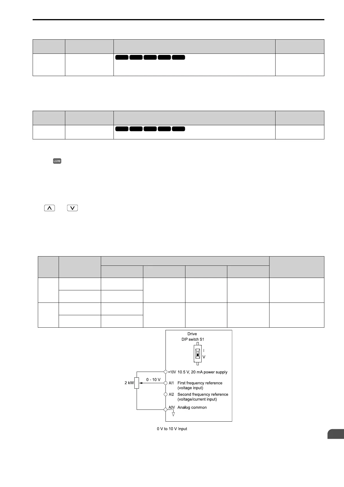
Use MFAI terminals AI1 and AI2 to input an analog frequency reference with a voltage or current input signal.
• Voltage Input
Refer to Table 12.8 to use a voltage signal input to one of the MFAI terminals.
Table 12.8 Frequency Reference Voltage Input
Terminal
Terminal Signal
Level
Parameter Settings
Note
Signal Level
Selection
Function Selection Gain Bias
AI1 0 - 10 V (Lower Limit
at 0)
H3-01 = 0 H3-02 = 4
[Freq Ref/BIAS]
H3-03 H3-04
-
0 - 10 V (Without
Lower Limit)
H3-01 = 1
AI2 0 - 10 V (Lower Limit
at 0)
H3-01 = 0 H3-10 = 4
[Freq Ref/BIAS]
H3-11 H3-12 Set DIP switch S1 to “V” for
voltage input.
0 - 10 V (Without
Lower Limit)
H3-01 = 1
Figure 12.17 Example of Setting the Frequency Reference with a Voltage Signal to Terminal AI1

 Loading...


