12.2 b: APPLICATION
472 SIEPCYEUOQ2V01A Q2V Technical Manual
■ b5-71: PID Fdbk 1/2 Selection
No.
(Hex.)
Name Description
Default
(Range)
b5-71
(01E6)
PID Fdbk 1/2 Selection
Selects the feedback configuration for PID control.
0
(0, 1)
0 : Feedback 1
The drive does D control on the difference between the feedback value and the PID setpoint output through U5-01
[PID Feedback].
1 : Feedback 2
The drive does D control on the difference between the feedback value and the PID setpoint output through U5-05
[PID Diff.Feedbk].
■ b5-72: PID D-FF Mode
No.
(Hex.)
Name Description
Default
(Range)
b5-72
(01E7)
PID D-FF Mode
Determines whether the D part is in the feedback path or used for feed forward control.
0
(0, 1)
0 : D=Fdback
The drive does D control on the feedback output through U5-06 [PID AdjustFeedback].
1 : D=FdFwd
The drive adds the frequency reference to the PID output. The drive does D control on the feedback output
through U5-06 [PID AdjustFeedback].
■ b5-02: Proportional Gain (P)
No.
(Hex.)
Name Description
Default
(Range)
b5-02
(01A6)
RUN
Proportional Gain (P)
Sets the proportional gain (P) that is applied to PID input.
1.00
(0.00 - 25.00)
Larger values decrease errors, but can cause oscillations. Smaller values let too much offset between the setpoint
and feedback.
Set b5-02 = 0.00 to disable P control.
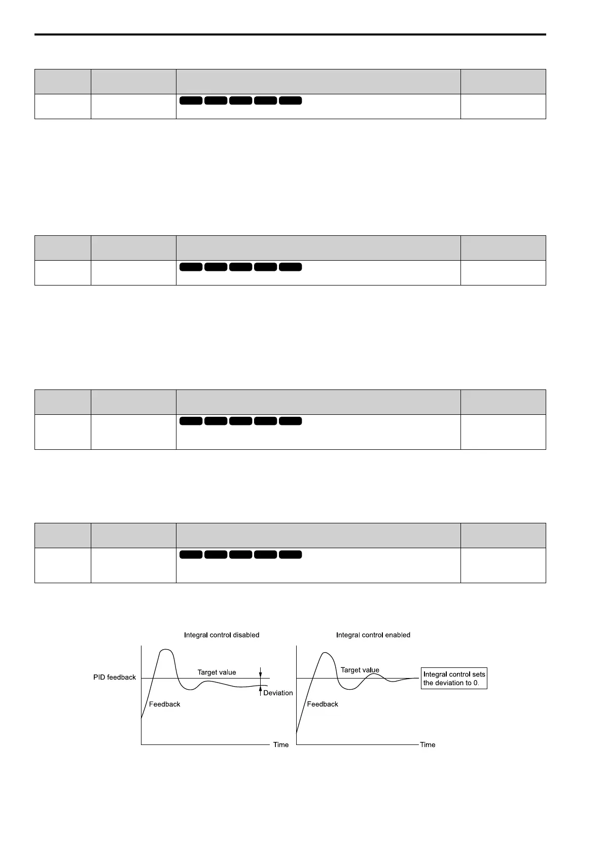
■ b5-03: Integral Time (I)
No.
(Hex.)
Name Description
Default
(Range)
b5-03
(01A7)
RUN
Integral Time (I)
Sets the integral time (I) that is applied to PID input.
1.0 s
(0.0 - 360.0 s)
Set a short integral time in b5-03 to remove the offset more quickly. If the integral time is too short, overshoot or
oscillation can occur.
Set b5-03 = 0.00 to disable I control.
Figure 12.33 Integral Time and Deviation

 Loading...


