Parameter Details
12
12.3 C: TUNING
SIEPCYEUOQ2V01A Q2V Technical Manual 489
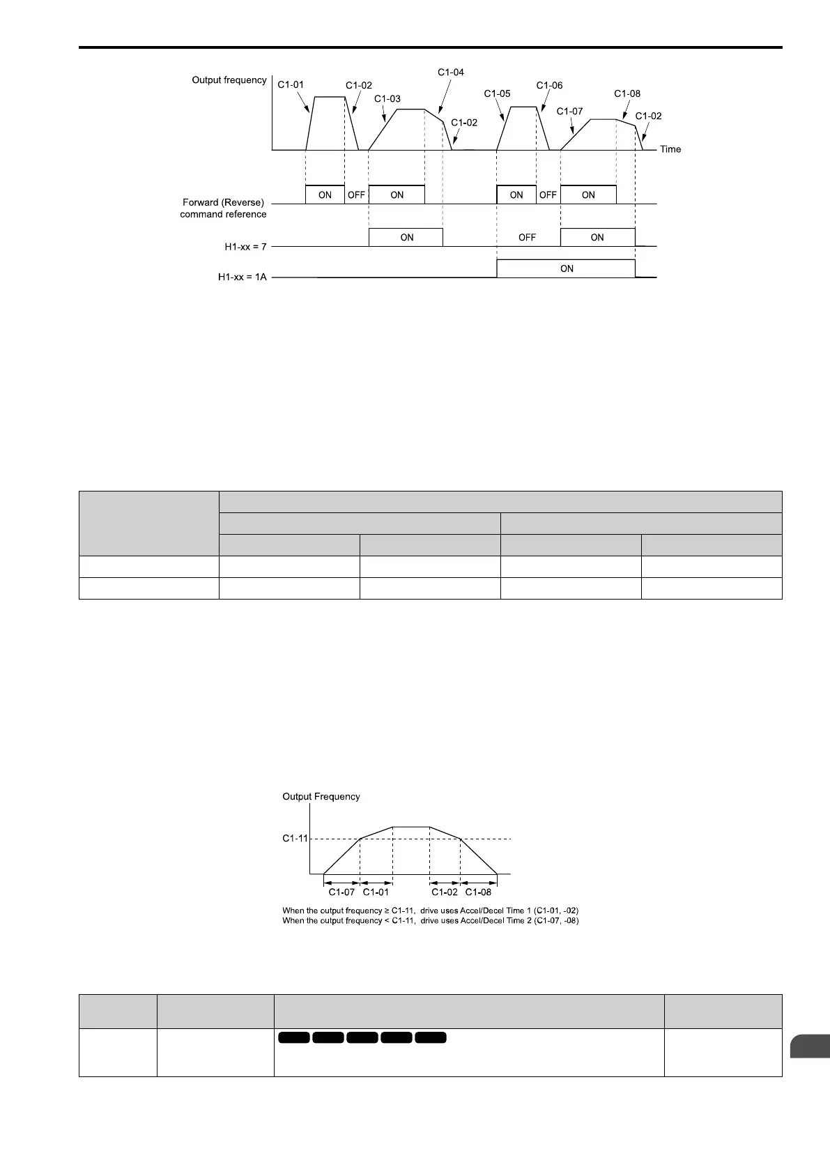
Figure 12.35 Timing Diagram of Acceleration and Deceleration Times
■ Use Motor Selection to Switch Acceleration and Deceleration Times
When you set H1-xx = 61 [MFDI Function Select = Motor 2 Select], you can activate and deactivate the input
terminal to switch between motor 1 and motor 2.
Note:
You cannot use the Motor 2 Selection function with PM motors.
Table 12.19 shows the possible acceleration and deceleration time combinations when you use the Motor 2
Selection function.
Table 12.19 Motor Selection and Acceleration and Deceleration Times
H1-xx = 18
[Ac/Dec Time1]
H1-xx = 61 [Motor 2 Select]
Motor 2 Selection: OFF Motor 2 Selection: ON
Acceleration Time Deceleration Time Acceleration Time Deceleration Time
OFF C1-01 C1-02 C1-05 C1-06
ON C1-03 C1-04 C1-07 C1-08
■ Use Output Frequency Level to Switch Acceleration and Deceleration Times
The drive can use output frequency to automatically switch between different acceleration and deceleration times.
When the output frequency = C1-11 [Accel/Decel Time Switchover Freq], the drive automatically switches the
acceleration and deceleration times. Set C1-11 = 0.0 Hz to disable this function.
Note:
• Acceleration and deceleration times set to MFDIs are more important than the automatic switch using the frequency level set in C1-11.
For example, if you set the switchover frequency to C1-11, the drive will not automatically switch acceleration and deceleration times
when the MFDI terminal set for Ac/Dec Time1 [H1-xx = 18] is activated.
• If Motor 2 Select [H1-xx = 61] is activated, the drive will set the acceleration/deceleration time to C1-05 and C1-06 for motor 2 when
the output frequency is more than the frequency level set in C1-11.
Figure 12.36 Accel/Decel Time Switching Frequency
■ C1-01: Accel Time 1
No.
(Hex.)
Name Description
Default
(Range)
C1-01
(0200)
RUN
Accel Time 1
Sets the length of time to accelerate from zero to maximum output frequency.
10.0 s
(0.0 - 6000.0 s)

 Loading...


