Parameter Details
12
12.4 d: REFERENCE
SIEPCYEUOQ2V01A Q2V Technical Manual 509
• When you set the voltage input of analog inputs from terminals AI1 and AI2 to 0 V to 10 V (Lower Limit at 0)
Procedure
Configuration
Parameter
Task Contents
1 Reference 1 1. Sets b1-01 = 1 [Freq. Ref. Sel. 1 = Analog Input].
2. Sets H3-02 = 3 [AI1 Function Selection = FrqBIAS Frq].
3. Sets H3-01 = 0 [AI1 Signal Level Select = 0 to 10V (Lower Limit at 0)].
2 Reference 2 1. Sets H3-10 = 1 [AI2 Function Selection = AuxFreqRef1].
2. Sets H3-09 = 0 [AI2 Signal Level Select = 0 to 10V (Lower Limit at 0)].
3 Signal type of analog input Set DIP switch S1 on the control circuit board to the V-side (voltage) to set terminal AI2 only for voltage input.
Note:
Set this before you energize the drive.
4
Reference 3 Sets the value of d1-03 [Reference 3].
5 Reference 4 Sets the value of d1-04 [Reference 4].
6 Reference 5 Sets the value of d1-05 [Reference 5].
7 Jog Reference Sets d1-17 [Jog Reference] to the jog speed.
8 External digital input (3
inputs)
Set the Multi-Step Speed Reference 1 to 3 [H1-xx = A, B, C] to one of the MFDI terminals DI1 to DI7.
9 JOG command Set the Jog Reference [H1-xx = 6] to one of the MFDI terminals DI1 to DI7.
Use the Maximum 17-Step Speed with All Digital Inputs
This section is the procedure to set the 17-step speeds (17 types of frequency references) without an analog input.
Procedure
Configuration
Parameter
Task Contents
1 Analog reference 1. Sets H3-02 = 0 [AI1 Function Selection = Through Mode], and disables the analog reference.
2. Sets H3-10 = 0 [AI2 Function Selection = Through Mode], and disables the analog reference.
2 Reference 2 to 16 Sets the values of d1-02 to d1-16 [Reference 2 to Reference 16].
3 Jog Reference Sets d1-17 [Jog Reference] to the jog speed.
4 External digital input (4
inputs)
Set Multi-Step Speed Reference 1 to 4 [H1-xx = A, B, C, D] to one of the MFDI terminals DI1 to DI7.
5 JOG command Set the Jog Reference [H1-xx = 6] to one of the MFDI terminals DI1 to DI7.
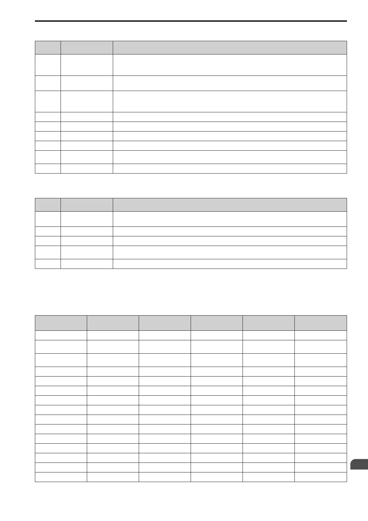
Multi-step Speed Operation Combinations
Refer to Table 12.26 and Figure 12.49 for information about multi-step speed reference combinations. The
selected frequency reference changes when the combination of digital input signals from an external source
changes.
Table 12.26 Multi-step Speed Reference and MFDI Terminal Combinations
Related Parameters
MultSpd Ref1
H1-xx = A
MultSpd Ref2
H1-xx = B
MultSpd Ref3
H1-xx = C
MultSpd Ref4
H1-xx = D
Jog Reference
H1-xx = 6
Reference 1 (set in b1-01)
OFF OFF OFF OFF OFF
Reference 2 (d1-02 or
terminals AI1, AI2)
ON OFF OFF OFF OFF
Reference 3 (d1-03 or
terminals AI1, AI2)
OFF ON OFF OFF OFF
Reference 4 (d1-04)
ON ON OFF OFF OFF
Reference 5 (d1-05)
OFF OFF ON OFF OFF
Reference 6 (d1-06)
ON OFF ON OFF OFF
Reference 7 (d1-07)
OFF ON ON OFF OFF
Reference 8 (d1-08)
ON ON ON OFF OFF
Reference 9 (d1-09)
OFF OFF OFF ON OFF
Reference 10 (d1-10)
ON OFF OFF ON OFF
Reference 11 (d1-11)
OFF ON OFF ON OFF
Reference 12 (d1-12)
ON ON OFF ON OFF
Reference 13 (d1-13)
OFF OFF ON ON OFF
Reference 14 (d1-14)
ON OFF ON ON OFF
Reference 15 (d1-15)
OFF ON ON ON OFF

 Loading...


