12.6 F: OPTIONS
548 SIEPCYEUOQ2V01A Q2V Technical Manual
Table 12.32 Specification
Item Specification
Applicable options All options that support the Modbus access function (for example, PROFIBUS-DP, PROFINET, EtherNet/IP, EtherCAT)
Compatible Products Drives that can set F6-16 [Gateway Mode]
*1
Number of connected drives Maximum: 5 units
Communication specifications Modbus (RTUmode) communications
Commands/responses The controller can send this data to each drive (Drive 0 to Drive 4):
• Control commands: Run commands and frequency references
• Control responses: Output frequency and drive status (during run, faults)
• Read and write parameters
• Read monitors
Synchronous control Not supported
*1 Gateway Mode is not available with Yaskawa 1000-series drives or previous series drives.
Note:
• The communication speed in gateway mode is slower than the speed in fieldbus communications. Make sure that the speed is
acceptable for your system.
• Response speed with the communication option is slower than with point-to-point communications.
• Set H5-03 [Mbus Parity] to the same value on the master drive and slave drives.
WARNING! Injury to Personnel. Separately prepare safety protection equipment and systems, for example fast stop switches. If
the motor does not stop correctly from the disconnection of communications cable or electrical interference, it can cause serious
injury.
Configuring Gateway Mode
The following table shows sample settings to connect 4 slave drives:
Table 12.33 Sample Settings for Using Gateway Mode
F6-16
[Gateway Mode]
H5-01
[Mbus Address]
*1
H5-02
[Mbus BaudRate]
H5-03
[Mbus Parity]
H5-06
[Mbus Tx Wait
Time]
H5-09
[Mbus CE Detect
Time]
b1-01
[Freq. Ref. Sel. 1]
b1-02
[Run Comm. Sel
1]
Drive 0
(Master Drive)
1 - 4
*2
1F (Default)
*5
5 ms (factory
default)
*6
≥ 2.0 s
*7
3 [Option PCB] 3 [Option PCB]
Drive 1
(Slave drive)
0 01
*3 *4 *5
5 ms (factory
default)
*6
≥ 0.9 s
*7
2 [Modbus]
*8
2 [Modbus]
*8
Drive 2
(Slave drive)
0 02
*3 *4 *5
5 ms (factory
default)
*6
≥ 0.9 s
*7
2 [Modbus]
*8
2 [Modbus]
*8
Drive 3
(Slave drive)
0 03
*3 *4 *5
5 ms (factory
default)
*6
≥ 0.9 s
*7
2 [Modbus]
*8
2 [Modbus]
*8
Drive 4
(Slave drive)
0 04
*3 *4 *5
5 ms (factory
default)
*6
≥ 0.9 s
*7
2 [Modbus]
*8
2 [Modbus]
*8
*1 Restart the drive to apply the new settings.
*2 Specify the number of slave drives you will connect.
*3 Setting 0 will not let the drive respond to Modbus communications.
*4 Set a slave address that is different from other slave devices.
*5 Enter the same value that you use for the master drive.
*6 To correctly detect the response timeout, do not change the value of H5-06 from the default value.
*7 Set H5-09 ≥ 0.9. When H5-09 < 0.9, the drive will detect CE [Modbus Communication Error] before it detects a response timeout.
*8 On each slave drive, set b1-01 [Freq. Ref. Sel. 1] and b1-02 [Run Comm. Sel 1] to 2 [Modbus].
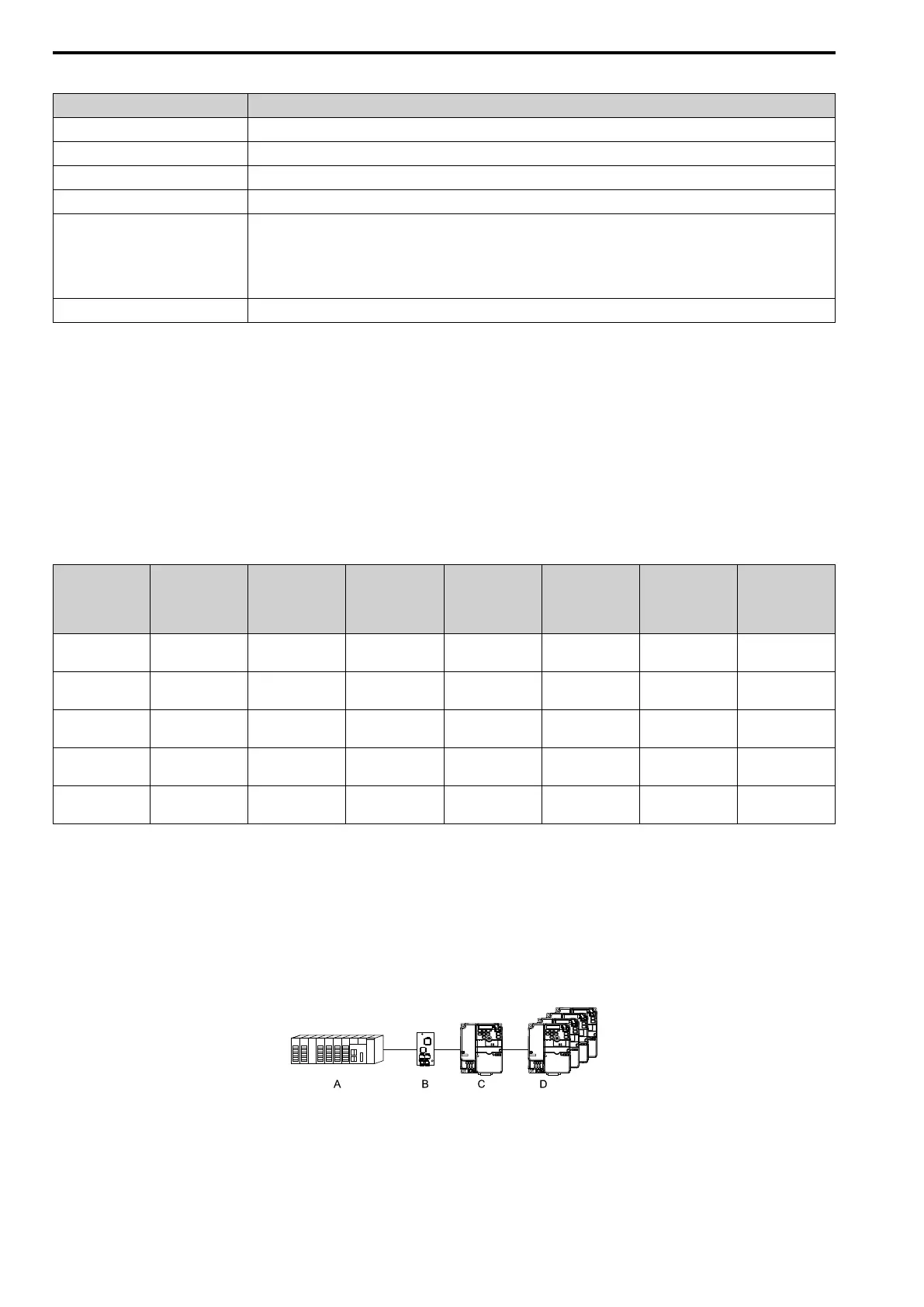
An Overview of Gateway Mode
When in gateway mode, the drive will operate as shown in Table 12.34.
A - Controller
B - Communication Option
C - Master Drive (Drive 0)
D - Slave Drives (Drives 1 to 4)

 Loading...


