Parameter Details
12
12.7 H: TERMINALS
SIEPCYEUOQ2V01A Q2V Technical Manual 605
Note:
• When L6-04 ≥ 5, the drive will detect when the output current/torque is less than the detection level of L6-05 for longer than the time
set in L6-06.
• Refer to “L6: TORQUE DETECTION on page 660” for more information.
■ 39: Timer Output
Setting Value Function Description
39 Timer Output
Use this setting when the drive uses the timer function as an output terminal.
Note:
Refer to “b4: TIMER on page 464” for more information.
■ 3C: Comparator 1
Setting Value Function Description
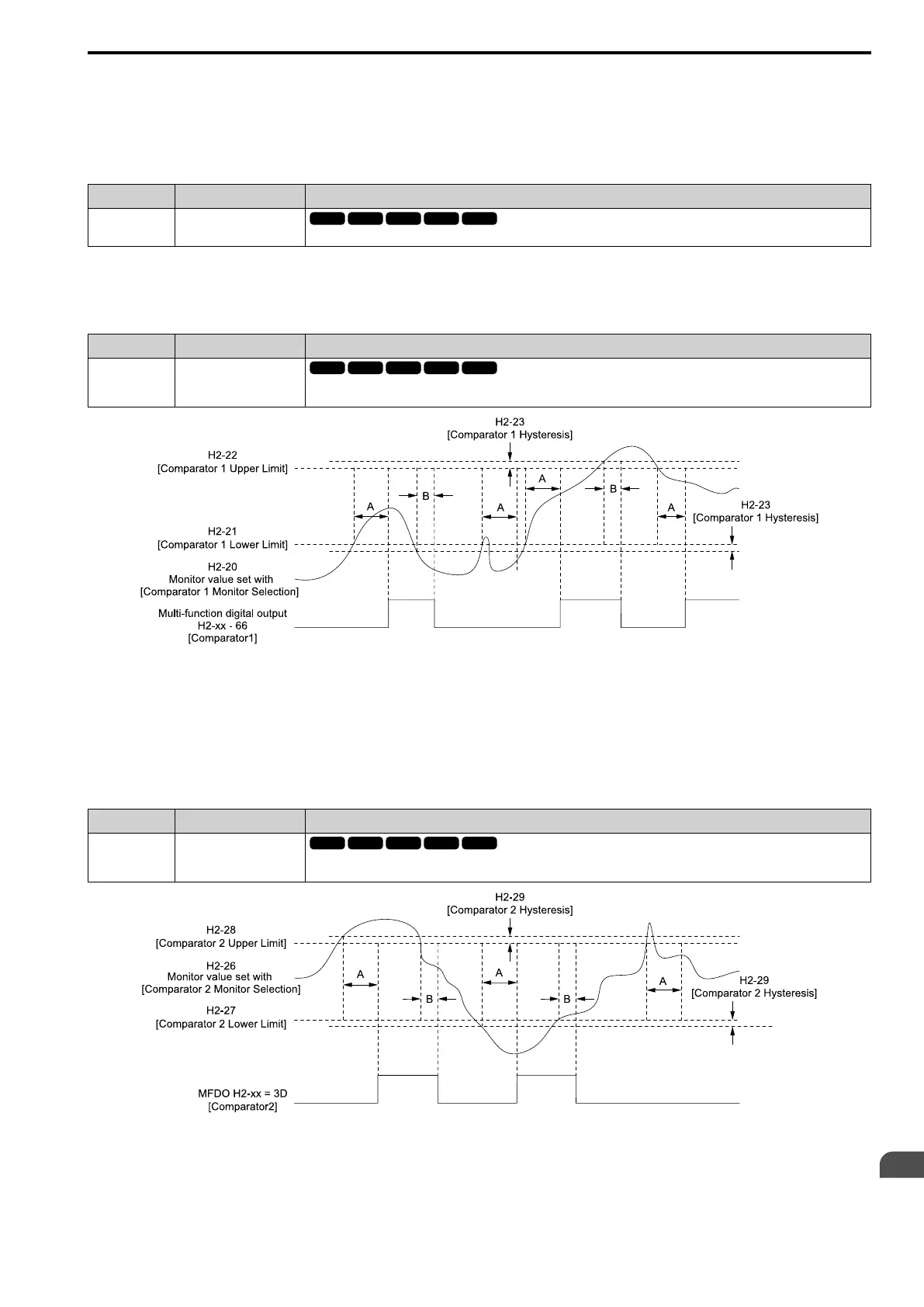
3C Comparator 1
The terminal activates if the monitor value set with H2-20 [Compare1 Mon.Selection] is in range of the values of H2-21
[Compare1 Low Limit] and H2-22 [Compare1 Up Limit] for the time set in H2-24 [Compare1 On-Delay Time].
A - H2-24
[Compare1 On-Delay Time]
B - H2-25
[Compare1 Off-Delay Time]
Figure 12.88 Comparator 1 Output Time Chart
Note:
The drive compares the monitors set with H2-20 as absolute values.
■ 3D: Comparator 2
Setting Value Function Description
3D Comparator 2
The terminal activates if the monitor value set with H2-26 [Compare2 Mon.Selection] is not in the range of the values of H2-27
[Compare2 Low Limit] and H2-28 [Compare2 Up Limit] for the time set in H2-30 [Compare2 On-Delay Time].
A - H2-30
[Compare2 On-Delay Time]
B - H2-31
[Compare2 Off-Delay Time]
Figure 12.89 Comparator 2 Output Time Chart

 Loading...


