Parameter Details
12
12.7 H: TERMINALS
SIEPCYEUOQ2V01A Q2V Technical Manual 609
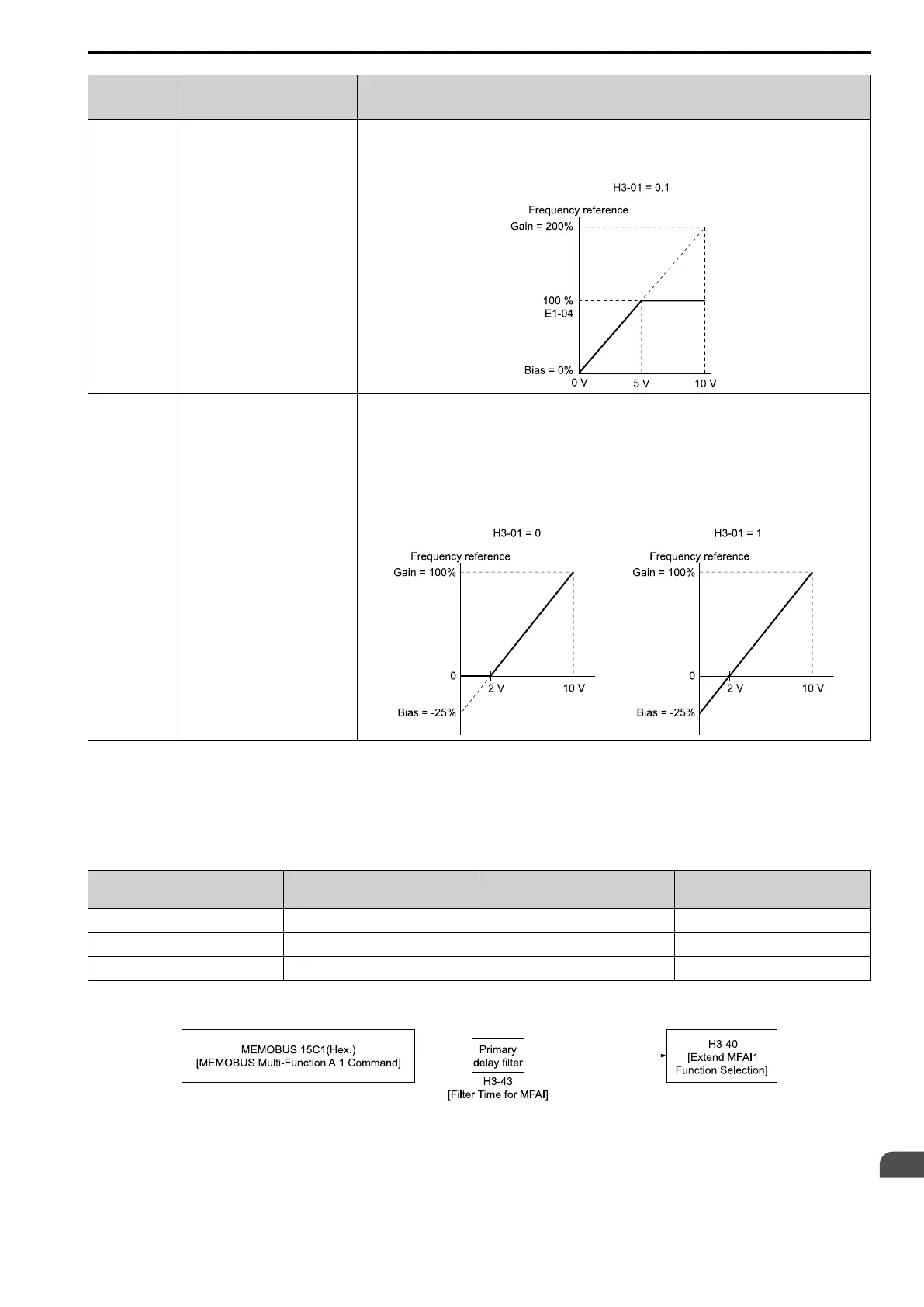
Example
Analog Input
Settings
Terminal AI1 Setting Frequency Reference
Frequency
Reference When
You Adjust the
Gain Setting
• H3-02 = 1 [AI1 Function
Selection= AuxFreqRef1]
• H3-03 = 200.0 [AI1 Gain Setting =
200%]
• H3-04 = 0.0 [AI1 Bias Setting =
0.0%]
• When you input a 10 V signal, the frequency reference will be 200%.
• When you input a 5 V signal, the frequency reference will be 100%.
When you input a 5 Vor more signal, E1-04 [Max Output Frequency] will limit the drive output and the frequency
reference will be 100%.
Frequency
Reference When
You Set the Bias
to a Negative
Number
• H3-02 = 1 [AuxFreqRef1]
• H3-03 = 100.0 [100.0%]
• H3-04 = -25.0 [-25.0%]
• When you input a 0 V signal, the frequency reference will be -25%.
• When H3-01 = 0 [AI1 Signal Level Select = 0 to 10V (Lower Limit at 0)]
– When you input a 0 V to 2 V signal, the frequency reference will be 0%.
– When you input a 2 V to 10 V signal, the frequency reference will be 0% to 100%.
• When H3-01 = 1 [0 to +10 V (Without Lower Limit)]
– When you input a 0 V to 2 V signal, it enables signals of positive and negative polarities and the motor
rotates in reverse.
■ Modbus Multi-Function AI1 to 3 Function Selection
You can set the MFAI function to Modbus register15C1 to 15C3 (Hex.) [Mbus Reg 15C1h through 15C3h Input
Function]. Use H3-40 to H3-42 [15C1h Input Function to 15C3h Input Function] to set the function and use H3-
43 [Mbus In FilterTime Const] to set the input filter.
Table 12.48 Modbus Multi-Function AI Command Register
Register No.
(Hex.)
Name Range
*1
Parameter
15C1 Mbus Reg 15C1h Input Function -32767 - +32767 H3-40
15C2 Mbus Reg 15C2h Input Function -32767 - +32767 H3-41
15C3 Mbus Reg 15C3h Input Function -32767 - +32767 H3-42
*1 Set as 100% = 4096.
Figure 12.90 Functional Block Diagram for Modbus Multi-Function AI Command 1

 Loading...


