EasyManuals Logo

Omron RX2 Series User Manual

Omron RX2 Series
920 pages
To Next Page IconTo Next Page
To Previous Page IconTo Previous Page
Page #111 background imageLoading...
Page #111 background image
2 - 57
2 Design
High-function General-purpose Inverter RX2 Series User’s Manual
2-3 Wiring
2
2-3-4 Wiring for Main Circuit Terminals
Wiring diagram for connecting two Regenerative Braking Units (Model: 3G3AX-RBU23)
P
P
N
SL1 SL2 AL1 AL2
RB
MA1 MA2
3G3AX-RBU23
P
P
N
SL1 SL2 AL1 AL2
RB
MA1 MA2
3G3AX-RBU23
ON
OFF
RY
RY
MC1
*1
R/L1
S/L2
T/L3
U/T1
V/T2
W/T3
P/+
N/-
1(AL1)
2(AL2)
P
RB
3G3AX-RBA
/RBB/RBC
1(AL1)
2(AL2)
P
RB
3G3AX-RBA
/RBB/RBC
MC1
MC2
MC2
MC1
MCCB
MC2
R
S
T
*2
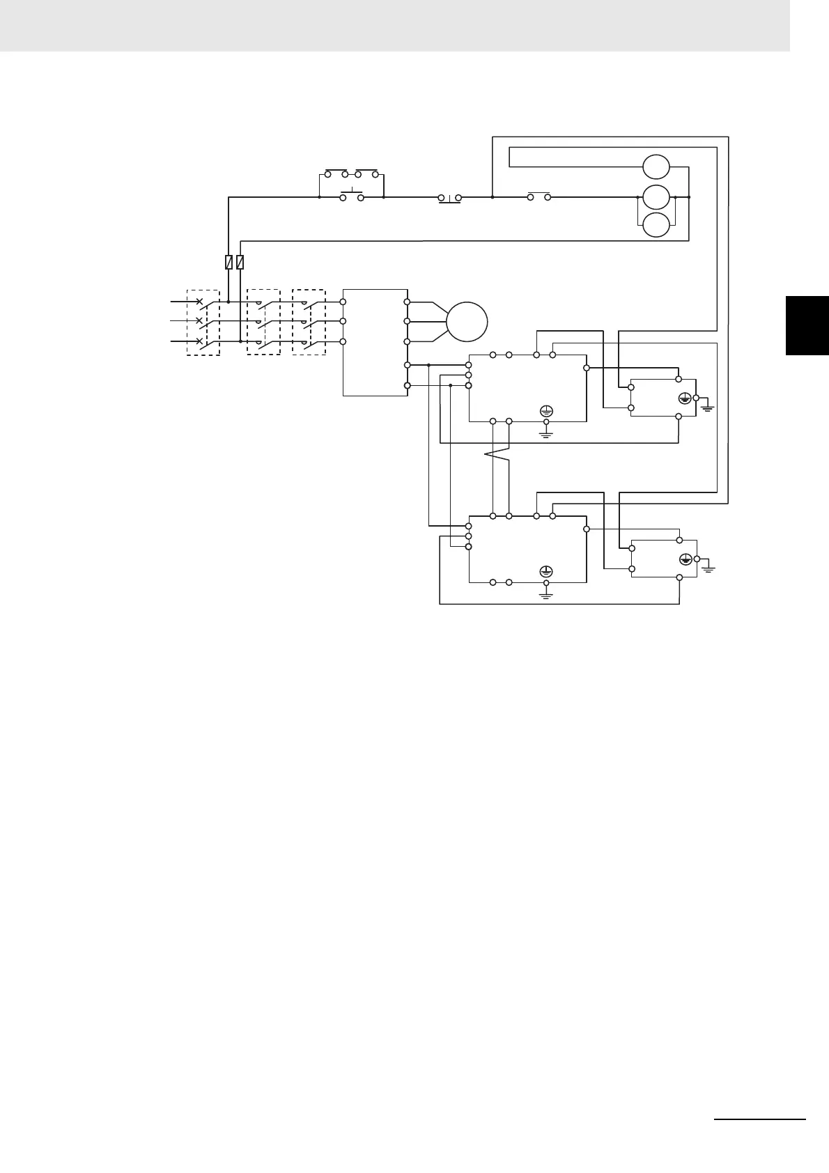
*1. For RY, select the contact rating according to the ratings of the coils MC1 and MC2.
*2. MC1 and MC2 are used not only to provide redundancy, but also to meet safety standards.
*3. You need to set DIP switch to regenerative braking unit as a slave, and wire terminal SL1 and SL2.
Fuse
3-phase 200 V
Inverter
Motor
Master
Regenerative braking unit
Slave*3

Table of Contents

Questions and Answers:

Question and Answer IconNeed help?

Do you have a question about the Omron RX2 Series and is the answer not in the manual?

Omron RX2 Series Specifications

General IconGeneral
BrandOmron
ModelRX2 Series
CategoryInverter
LanguageEnglish

Related product manuals