2 Design
2 - 58
High-function General-purpose Inverter RX2 Series User’s Manual
Precautions for Correct Use
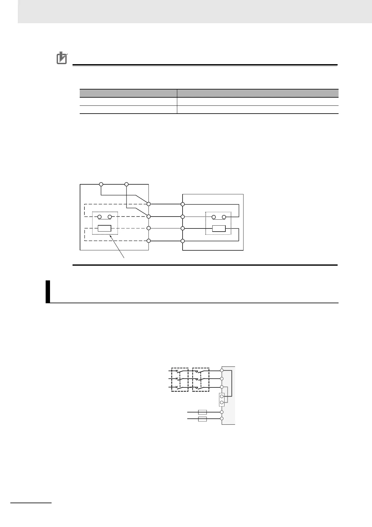
• Each braking resistor has alarm contact (thermal relay output) terminals as shown below. Be
sure to perform wiring for these terminals.
• To remove the built-in register from the Regenerative Braking Unit with a Built-in Braking
Resister (Model: 3G3AX-RBU21/RBU22/RBU41) in order to use the Braking Resistor
(Model: 3G3AX-RBA/RBB/RBC), remove the wiring of thermal relay for the built-in resistor
and connect the alarm contact (thermal relay output) terminals of the braking resistor with the
terminals R1 and R2.
If the inverter protection circuit is activated to shut off the magnetic contactor of the input power supply,
the power to the inverter control circuit is also turned off, and the alarm signal [AL] cannot be retained.
If the alarm signal must be retained, use control circuit power supply terminals Ro and To. Connect con-
trol circuit power supply terminals Ro and To with the primary circuit of the magnetic contactor accord-
ing to the following procedure.
Model Alarm contact terminals
3G3AX-RBA/RBB Between terminal 1 and terminal 2
3G3AX-RBC Between terminal AL1 and terminal AL2
Connection for Separating Inverter Control Circuit Power Supply
from Main Power Supply
AL1 AL2
R1
R2
P
RB
1(AL1)
2(AL2)
P
RB
Remove the built-in register.
External braking resistor
(Model: 3G3AX-RBA/RBB/RBC)
Regenerative braking unit built-in braking resister
(Model: 3G3AX-RBU21/RBU22/RBU41)
Resistor
Resistor
Earth leakage
breaker
Electromagnetic
contactor
3-phase
AC power
supply
3A fuses
Control circuit
power supply
(1) Disconnect the connected wire to
R0 and T0.
(2) Disconnect the J51 connector.
(3) Connect the control circuit power
supply cable to R0 and T0.
(Connection method)
Receiving electricity specifications
200-V class:
200 to 240 VAC (+10%, –15%)
(50/60 Hz ±5%)
(282 to 339 VDC)
400-V class:
380 to 500 VAC (+10%, –15%)
(50/60 Hz ±5%)
(537 to 707 VDC)
 Loading...


