2 - 61
2 Design
High-function General-purpose Inverter RX2 Series User’s Manual
2-3 Wiring
2
2-3-5 Wiring for Control Circuit Terminals
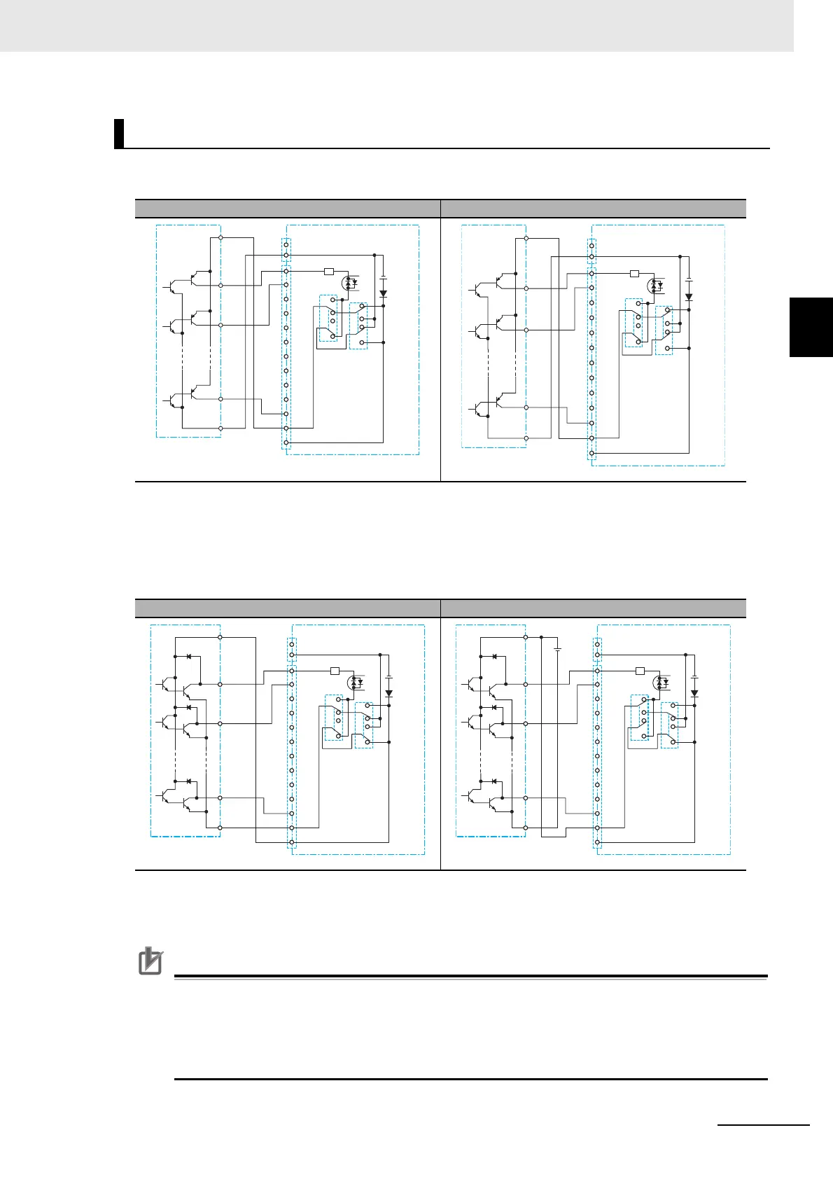
Source Logic
• If you apply the inverter’s internal power supply, set SW5 to IN.
• If you apply the external power supply, set SW5 to EXT.
• If you connect output unit of source type, set SW6 to SRC.
Sink Logic
• If you apply the inverter’s internal power supply, set SW5 to IN.
• If you apply the external power supply, set SW5 to EXT.
• If you connect output unit of sink type, set SW6 to SINK.
Precautions for Correct Use
• Confirm the SW6-position for switching the sink/source logic, before turning on the main
power supply. Not doing so may result in damage of the inverter or its peripheral unit.
• Make sure you must turn on the programmable controller and its external power supply at
first before you turn on the inverter’s power supply. Otherwise inverter’s inner data may be
altered.
Input Terminals and Programmable Controller Connection
When inverter’s internal power supply is applied When external power supply is applied
When inverter’s internal power supply is applied When external power supply is applied
COM
S
P+
P−
1
CM1
DC24V
2
3
4
5
6
IN
EXT
SRC
SW5 SINK
SW6
7
8
9
A
B
COM
P24
+
COM
S
P+
P−
1
CM1
DC24V
2
3
4
5
6
IN
EXT
SRC
SW5 SINK
SW6
7
8
9
A
B
COM
P24
+
P+
+
P−
1
CM1
DC24V
2
3
4
5
6
IN
EXT
SRC
SW5 SINK
SW6
7
8
9
A
B
COM
P24
S
COM
P+
DC24V
+
−
P−
1
CM1
DC24V
2
3
4
5
6
IN
EXT
SRC
SW5 SINK
SW6
7
8
9
A
B
COM
P24
S
COM
+

 Loading...


