2 - 69
2 Design
High-function General-purpose Inverter RX2 Series User’s Manual
2-3 Wiring
2
2-3-6 Wiring for PG Option Unit
The wire length between the encoder and PG Option Unit must be 20 m or shorter.
Use twist pair for the signal line.
When you connect cables, we recommend you to connect an encoder’s shielded wire to EG terminal on
PG Option Unit. If the cable is not shielded properly, the inverter may incorrectly perform due to the
influences of external noises. Generally, shield wires are connected to common signal terminal or chas-
sis earth terminal. However do not connect at multiple points.
Connect FG terminal of PG Option Unit to Function Ground.
If you link-up the encoder power supply terminal of PG Option Unit by relay amplifier, distance among
the relay amplifier, PG Option Unit must be 20 meters or shorter.
When you connect a cable between the relay amplifier and PG Option Unit, we recommend you to con-
nect the shielded wire to EG terminal at PG Option Unit.
As for the connection between relay amplifier and encoder (connecting method and cable length), ask
and confirm the input specifications of relay amplifier to the producer before connecting.
In case the wiring to PG Option Unit exceeds 20 meters, the inverter performs improperly due to the
influences of external noise. Take a special care for the wiring of relay amplifier for it.
When you supply the power to the encoder from devices other than PG Option Unit, connect the com-
mon of encoder power supply (basic potential) to EG terminal at PG Option Unit.
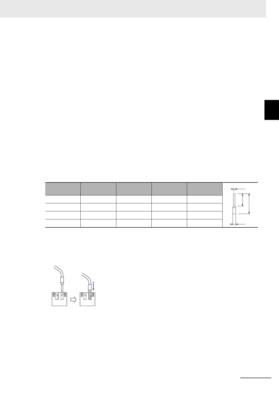
Recommending Terminals
For the improvement of easy wiring and credibility, we recommend those pin-terminals shown in the
table below for signal lines.
Note Those specifications above are different from the recommended pin-terminals for the inverter’s main body.
Insertion Method
Insert the pin-terminal to the terminal block of PG Option Unit. A proper pin-terminal can be inserted
without tools.
In case you use improper pin-terminals, insert the cable by the order of steps of pull-out method with
a flathead screwdriver shown below.
Wire size
mm
2
(AWG)
L1 [mm] L2 [mm] Φd [mm] ΦD [mm]
0.25 (24) 10.0 14.5 0.8 2.0
0.34 (22) 10.0 14.5 0.8 2.0
0.5 (20) 10.0 16 1.1 2.5
0.75 (18) 10.0 16 1.3 3.4
Φd
Φ
D
L2
L1

 Loading...


