3 Operation
3 - 10
High-function General-purpose Inverter RX2 Series User’s Manual
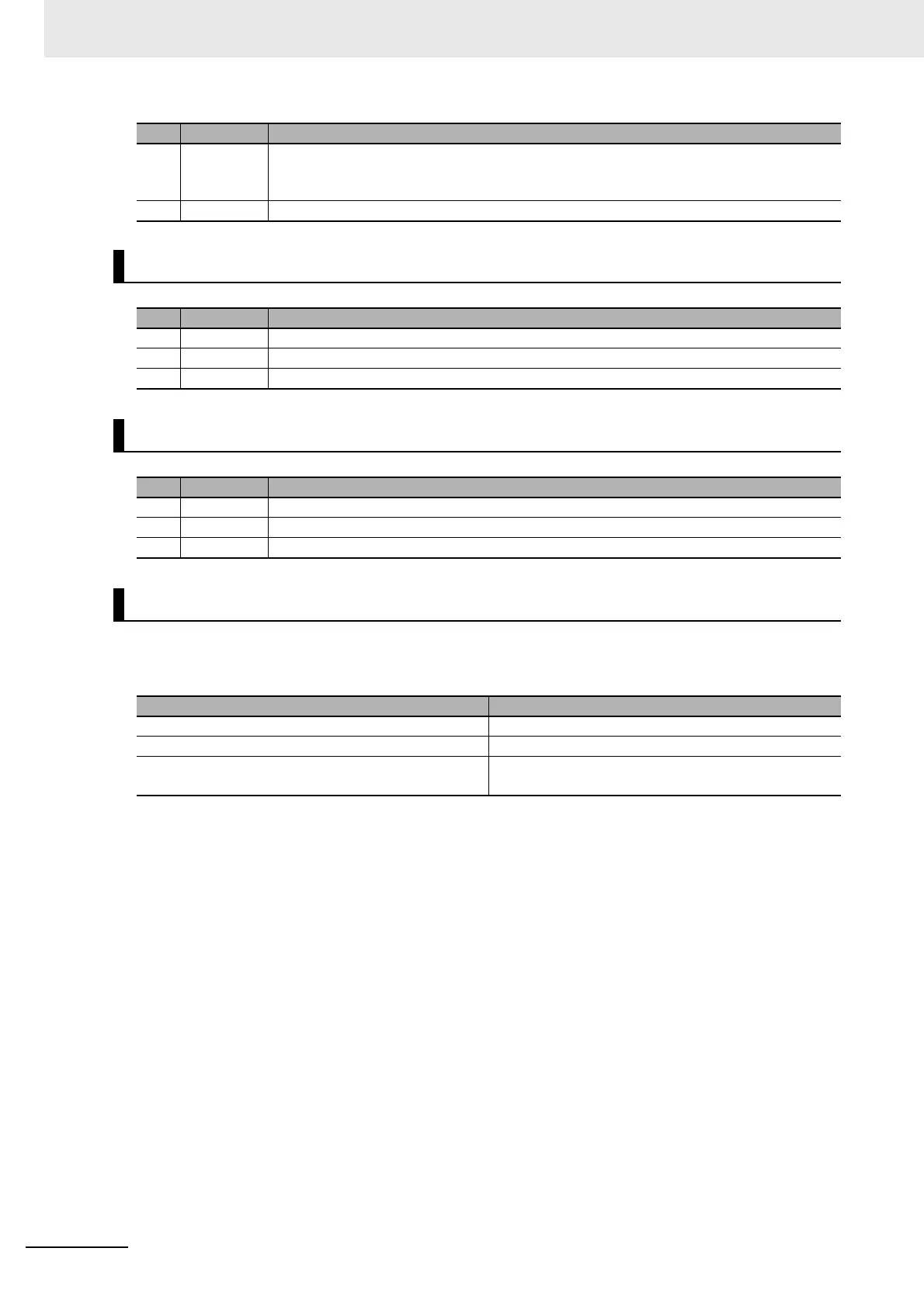
For LCD display backlight, two colors are provided: white and orange.
Colors varying depending on the inverter’s status are shown in the table below:
e7 P-2C From the status that the operation of ST1 and ST2 are both STO (contact point OFF), ST1
transitions to be operation-allowed (contact point ON), and later ST2 is kept STO (contact
point OFF) for the STO switching allowable time [bd-02].
e8 STO ST1 and ST2 are both in the STO status (contact point OFF).
Display <f>: Control Command Mode Display
No. Indication Description
f1 (None) The speed control mode.
f2 TRQ The torque control mode.
f3 POS The position control mode.
Display <g>: DriveProgramming Operation Mode Display
No. Indication Description
g1 (None) DrivePrograming is not selected.
g2 Ez_S DrivePrograming is stopped
g3 Ez_R DrivePrograming is working
LCD Display Backlight
Backlight color Status
White Normal (not related to inverter’s operation and stop)
Orange Warning (parameter discrepancy)
White and orange
(blinking alternatively at one-second interval)
Trip (equivalent to alarm LED)
No. Display Description
 Loading...


