6 Basic Parameter Settings
6 - 30
High-function General-purpose Inverter RX2 Series User’s Manual
Monitor (Main Body)
Internal Arithmetic Block Diagram
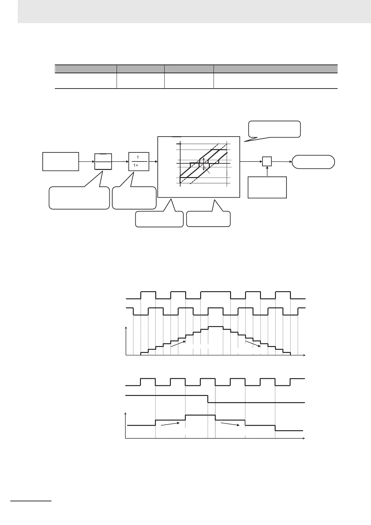
Internal processing is schematically drawn.
Details about Pulse String Input Mode
Command frequency is determined by the frequency of the pulse string input.
The sign of the command frequency is determined in the following way.
a) Mode 0: [CA-91]=00 90° phase difference pulse string
b) Mode 1: [CA-91]=01 forward and reverse rotation commands + pulse string
Item Parameters Data Description
Pulse string input mon-
itor (main body)
[dA-70]
-100.0 to
100.00(%)
The frequency command from the pulse string
input (input terminals A/B) is displayed.
Pulse string
frequency
acquisition
Max. frequency
Pulse string frequency
scale G [CA-92]
(0.05kHz-32.00kHz)
Filter time constant T
[CA-93]
(0.01s-2.00s)
Upper limit [CA-95]
(0.00%-100.00%)
Frequency
command
Bias [CA-94]
(-100.00%-100.00%)
Bias, limit, cut
Limit
Cut
Output
Input
Limit
Cut
Lower limit [CA-96]
(0.01%-100.00%)
Frequency
Bias
Pulse string frequency processing block
Terminal
[A]
Time
Positive (+)
Negative (-)
Terminal
[B]
Number of
detected pulses
Pulse string
input
Pulse string
input
Time
Positive (+)
Negative (-)
Terminal
[B]
Number of
detected pulses
Terminal
[A]
Pulse string
input
Forward/Reverse
rotation command

 Loading...


