7 - 27
7 Advanced Settings
High-function General-purpose Inverter RX2 Series User’s Manual
7-2 Selection of Motor Control Methods
7
7-2-11 Synchronous Motor (Permanent Magnet Motor) Control
Precautions for Correct Use
• Some SM (PMM) may be unable to start in the IVMS start mode.
• For IVMS control mode, you are required to make a precise adjustment. By using the
auto-tuning selection[AH-01]=03, check that the target motor can be operated by IVMS con-
trol. If the auto-tuning result is NG, you need to find other control modes because the target
motor cannot be operated by IVMS control.
• IVMS start mode requires a re-adjustment when the inverter is replaced. When a malfunc-
tioning inverter needs to be restored immediately by replacing the malfunctioning inverter
with a new one, the synchronous starting mode should be used.
• As the IVMS start mode is a very special control, which may make a unique operation sound
as the starting sound.
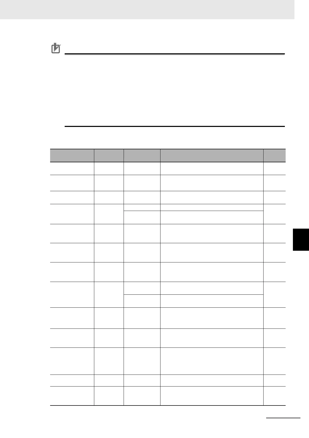
Parameters for IVMS Start Mode
Item Parameter Data Description
Default
data
Carrier frequency
at IVMS
[Hd-41]
0.5 to
16.0(kHz)
Set the carrier frequency during the IVMS drive.
Usually, the value does not require to change.
2.00
Filter gain of cur-
rent detection at
IVMS
[Hd-42] 0 to 1000
The filter adjustment gain applied to the detec-
tion current during the IVMS drive.
100
Open phase volt-
age detection gain
[Hd-43] 00 to 04
The adjustment gain applied to the detection
voltage during the IVMS drivel.
00
Open phase
switching thresh-
old compensation
[Hd-44]
00 IVMS correction: Disabled (no correction)
01
01
IVMS correction: Enabled (correction to be con-
ducted)
P-Gain for speed
control,
SM(PMM)-IVMS
[Hd-45] 0 to 1000
Speed control P gain during the IVMS drive A
larger value enhances the responsiveness of
the speed control.
100
I-Gain for speed
control,
SM(PMM)-IVMS
[Hd-46] 0 to 10000
Speed control I gain during the IVMS drive A
larger value enhances the responsiveness of
the speed control.
100
Wait time for open
phase switching,
SM(PMM)-IVMS
[Hd-47] 0 to 1000
Waiting time for the open-phase switching
during the IVMS drive. A larger value enhances
the stability.
15
Limitation of deci-
sion about the
drive direction,
SM(PMM)-IVMS
[Hd-48]
00
Rotation-direction determination: Disabled (no
restriction)
01
01
Rotation-direction determination: Enabled
(restricted to the operation-command direction)
Open phase volt-
age detection tim-
ing adjustment,
SM(PMM)-IVMS
[Hd-49] 0 to 1000
Adjustment value of the IVMS detection timing.
Usually, the value does not require to change.
10
Minimum pulse
width adjustment,
SM(PMM)-IVMS
[Hd-50] 0 to 1000
To adjust the width of the voltage pulse during
the IVMS drive. A larger value renders the pulse
width wider.
100
IVMS Current Limit
for threshold
[Hd-51] 0 to 255
Set a limit on each of the upper and the lower
limits of the detection current during the IVMS
drive.
Ena
b
led when [Hd-44] = 01 (enabled).
100
IVMS Threshold
Gain
[Hd-52] 0 to 255 To adjust the IVMS auto-tuning value. 100
IVMS Carrier fre-
quency start/end
point
[Hd-58] 0 to 50(%)
To adjust the point where the carrier frequency
is switched in the IVMS start mode. Usually, the
value does not require to change.
5