7 - 39
7 Advanced Settings
High-function General-purpose Inverter RX2 Series User’s Manual
7-2 Selection of Motor Control Methods
7
7-2-16 Encoder Feedback Control
Precautions for Correct Use
• When either [CA-82] or [ob-02] = 00, meaning that phase-A is leading, and when the opera-
tion is of forward rotation, the phase of the phase-A advances 90-degrees more than that of
the phase-B in a normal case.
• When either [CA-82] or [ob-02] = 01, meaning that phase-B is leading, and when the opera-
tion is of forward rotation, the phase of the phase-B advances 90-degrees more than that of
the phase-A in a normal case.
• To check if the encoder input into the main body or into PG option unit is correct, set [AA121]
= 00 to 03, meaning V/f control (00), and check the monitor for the [dA-08] frequency detec-
tion values. The wiring is correct if the forward operation [FW] has a positive (+) value and if
the reversal operation [RV] has a negative (-) value. If it is incorrect, either revising the wiring
or switching the Encoder position selection [CA-82] or [ob-02].
When the encoder and the motor shaft are connected to each other by means of a gear, for Tables (3)
and (4) conversion is made possible by setting up (3) Encoder gear-ratio’s numerator/(4) encoder
gear-ratio’s denominator.
Set the values ((3)/(4)) so as to be within a range between (1/50) to (20).
An exemplar case where a gear is attached there.
When the encoder’s rotating rate for the motor’s standard encoder becomes 1/10 for 1024 pulses,
Table (1) Encoder constant set-up: 1024 pulses
Table (3): Encoder’s gear ratio’s numerator: 1.
Table (4): Encoder’s gear ratio’s denominator: 10
Set up as above.
To acquire the frequency that was input through the encoder, the following settings are necessary.
• Set-up of Tables (1), (3), and (4)
• Set-up of the number of motor poles
Note When the selected control mode [AA121] is the induction motor control ([AA121] = 00 to 10), async.Motor
poles setting, 1st-motor [Hb103] is set as the number of motor poles.
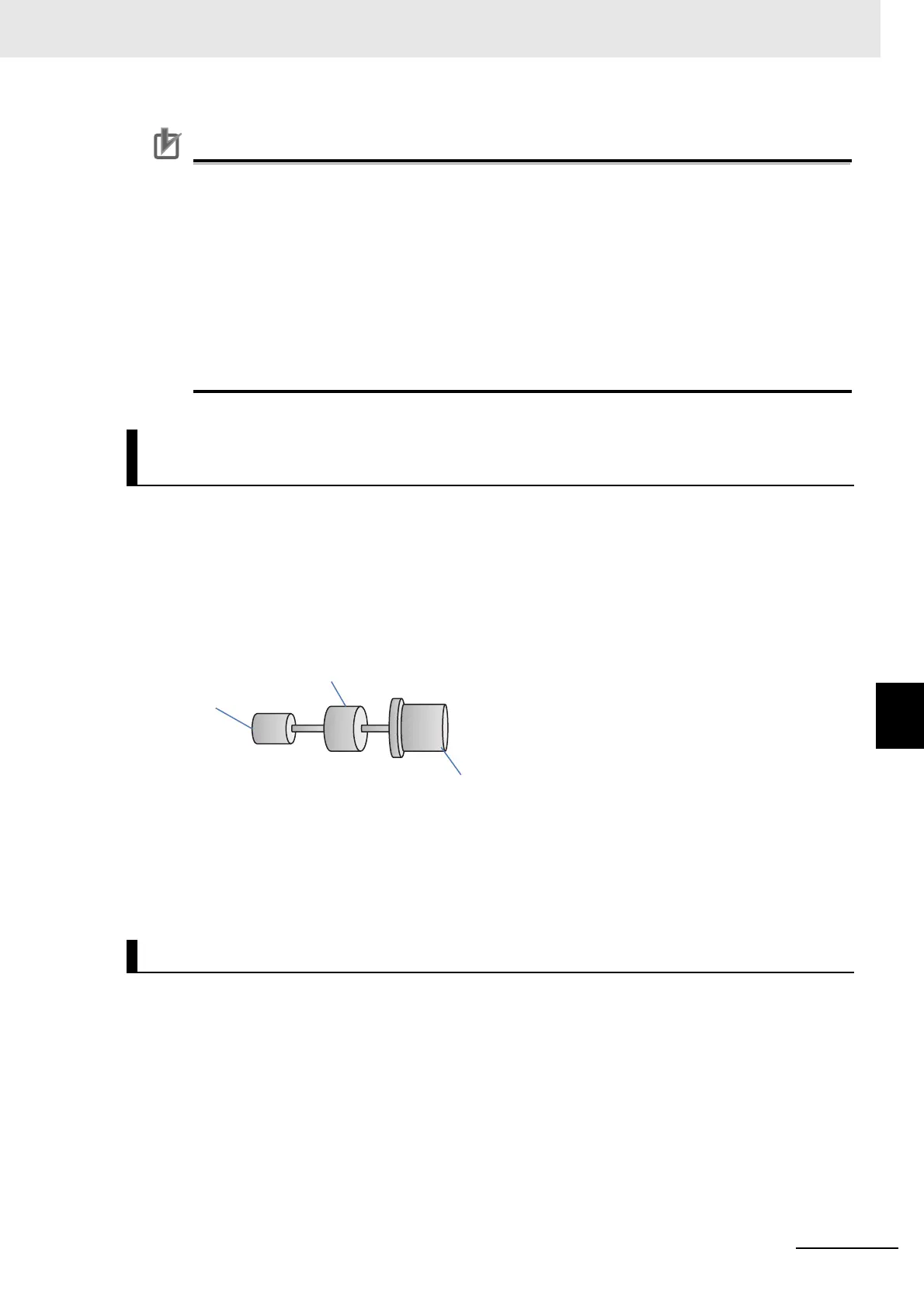
Adjustment in Cases Where a Gear Exists between the Motor and
the Encoder
Encoder’s Speed Detection
Gear
(Load side/motor-side = 1/10)
Encoder
(1024pulse)
Motor
 Loading...


