8 - 17
8 Applied Settings
High-function General-purpose Inverter RX2 Series User’s Manual
8-1 PID Control
8
8-1-2 PID Parameter and Block Diagram
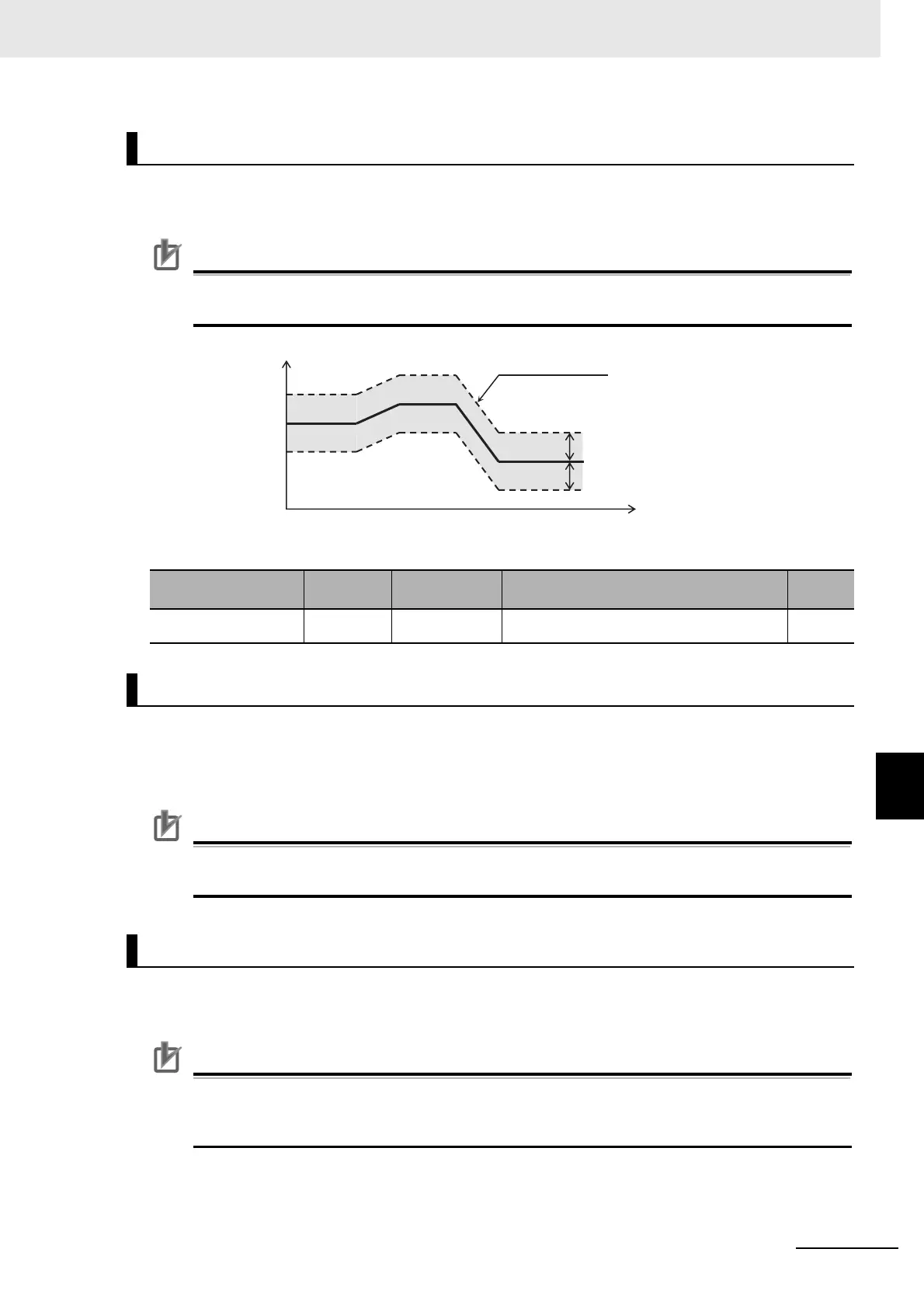
PID output is restricted to a changeable range based on the target value.
When [AH-71] is 0.00, the function will be disabled.
Precautions for Correct Use
In the case of using this function, set PID1 output range [AH-71]. Restriction will be made in a
range of PID target value ± [AH-71] with the maximum speed as 100%.
Parameter
In normal PID control, the inverter does not output a negative figure for frequency command and limits
at 0 Hz, when result of PID calculation was negative. If you select 02 (with reverse output) for PID1
selection [AH-01], frequency command can be output in a reverse direction, when result of PID calcula-
tion was negative.
Precautions for Correct Use
When [AH-01] is set to 02 (with reverse output), the PID changeable range limit function
[AH-71] will be extended to the negative direction.
This is a function to clear the integral figure of PID operation.
In the case of turning ON the [PIDC] terminal, do so when PID is not in operation.
Precautions for Correct Use
Turning ON the [PIDC] terminal during PID operation clears the integral value added to the PID
output command and changes the PID output command value abruptly, resulting in an
over-current error.
PID1 Changeable Range Limitation
Item
Terminal
name
Data Description
Default
data
PID1 output range [AH-71]
0.00 to
100.00(%)
Changeable range based on the target value 00
PID1 Reverse Output
PID1 I Control Integral Reset Function [PIDC]
PID changeable range [AH-71]
PID changeable range [AH-71]
Time (s)
PID output range
PID output (%)
PID target value
 Loading...


